Wireless weather station - open hardware and open source hobby construction
Since the weather station which I operate at www.pittnerovi.com/meteo has been in reliable service for a couple of years, I decided to build another one and place it at a weekend cottage ( www.pittnerovi.com/meteo1), taking advantage of the price decline of machine-2-machine cellular data tariffs.Update 2020: Using RFM22B transceiver in the meteostation/thermostat board
I have developed a new version of the board, which employs the RFM22B transceiver using its 'direct modulation' mode instead of the Aurel RX433 and TX433 modules - in a fully compatible way. PDF schematics is meteo7.pdf and the open hardware board design files in Kicad are meteo7.zip. Software supporting RFM22B setup in direct mode and connection to MCU as done on this board is published here under GNU GPLv3 license in the file meteo4.c . It was quite simple to adapt it, just porting the RFM22 setup routines from a previous code supporting RFM22B on ARM LPC111x to ATmega128.Update 2020: Using wind sensors from WH1080
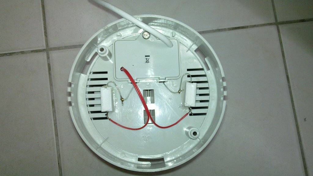
Since the TX20 anemometer on one of my meteostations became faulty due to aging and unfortunately its manufacture has been discontinued, I was seeking for an replacement. One possibility was to use wind sensors from the popular meteostation WH1080, which can be purchased as spare parts either separately, or as the whole external unit. I purchased the whole external unit and analyzed its wireless communication protocol, as well as how the wind sensors operate and support both in the software. I was definitely not the first one hacking with WH1080, so a lot of material was already available on the internet and I give reference links below.Receiving wireless transmission from the external sensors of the WH1080 meteostation
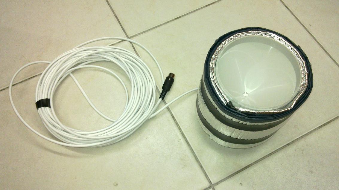
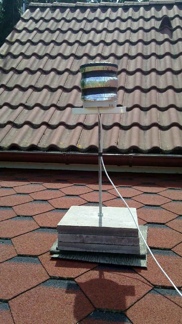
There are several versions of the popular WH1080 weather station, which vary in the transmission frequency (433, 868, 915 MHz) and the modulation (OOK, FSK). My one happened to employ the OOK modulation in the 868 band, using a SDR receiver and gnuradio as a spectrum analyzer I found the exact carrier frequency to be 868.350MHz and modulation OOK. As I built already previously an ISM band transceiver with ethernet interface, based on RFM22B and LPC1114, the only remaining task was to write a code that will demodulate OOK and decode the datagrams from the meteostation and forward them as UDP packets over LAN to the server.The WH1080 protocol for devices using FSK (which was not my case) was described here The WH1080 transmitting in OOK modulation does not send the preamble and sync word like this, but the payload structure is essentially compatible. The only difference I noted in the payload was in temperature (integer in 0.1C multiples), which was shifted by 400 rather than coded with a sign bit.
The OOK modulation of WH1080 was described already here To be selfcontained in the description here, I note:
A pulse-width modulation on top of OOK is employed. The logical one is encoded as a short high/low pulse of duration about 500us high and 500us low. The logical zero is encoded as a longer high/low pulse of duration about 1500us high and 1000us low. The datagram consists of a preamble of 7 one-bits and then 80 payload bits (possibly 8 preamble bits are transmitted and the first one was never captured by the RFM22 receiver in my setup). MSB bits of each byte are transitted first, LSB bits last. Checksum is a CRC8 with polynomial 0x31, xoring the input data first, computed from bytes 0-8 of the payload, stored in byte 9 of the payload. I employed the ``direct'' modulation mode of RFM22 and did all the demodulation in the MCU, as this is not compatible with the native packet mode of RFM22. I used RX bandwidth 150000Hz and data rate 2000Hz, see code for all the parameters and register setup of RFM22.
The decoding of the payload worked exactly as described in the links above for both meteo messages and DCF messages. My station sends meteo messages cca every minute and DCF messages after every even hour, repeated 5 times.
The resulting code (released under GNU GPLv3) for the receiver, which also decodes the messages and prints them to UART, is WH1080_eth_interface.c from the collection arm_lpc111x.tar.gz.
I have modified the outer transmitter unit of WH1080 to power it from a DC power supply rather than batteries, as I have no desire to climb the roof in the winter to replace batteries :-). I have specifically used an old-fashioned transformer-based DC adapter and made a linear stabilizer to 3V with LM317T. This is because most switch-mode adapters produce too high noise in the frequency band of 70kHz that they virtually scramble it and make DCF reception by the powered device impossible. I had this experience already previously with powering DCF clocks.
Using wind sensors from the WH1080 meteostation directly with my meteostation hardware
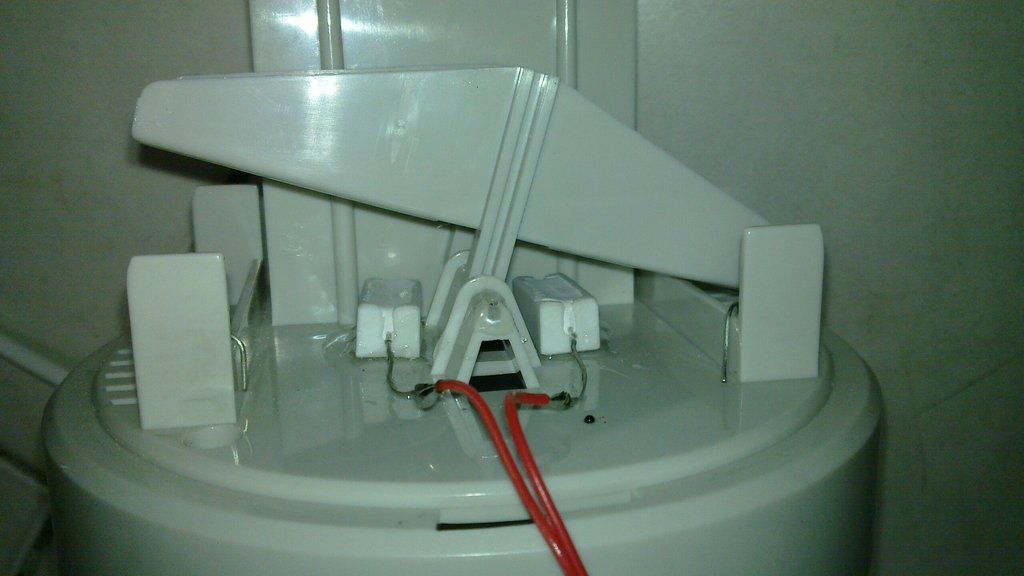
The wind sensors of WH1080 are very simple ``dumb'' sensors, which is positive, since they are not expensive and can be easily interfaced to any microcontroller. They have been described already, but as far as I know only in the czech language here. I thus give a brief description here.The speed sensor is connected to the two middle pins (2,3) of the RJ11 connector and contains a relay contact, which is activated by magnets every 180 degrees of rotation of the anemometer, which corresponds to about 0.66 m/s per 1Hz. The dependence will certainly not be linear in the whole range of measurable speeds, but no accurate calibration is known.
The wind direction sensor is connected to the two outer pins 1,4 of the RJ11 connector, and internally the sensor connects various resistors to the pins, as follows:
| Direction |
Resistance |
| 0 | 29800 |
| 22.5 | 6630 |
| 45 | 8270 |
| 67.5 | 881 |
| 90 | 1000 |
| 112.5 | 688 |
| 135 | 2200 |
| 157.5 | 1403 |
| 180 | 3920 |
| 202.5 | 3156 |
| 225 | 15800 |
| 247.5 | 14038 |
| 270 | 66500 |
| 292.5 | 36200 |
| 315 | 48500 |
| 337.5 | 21050 |
Note that the angles of odd multiples of 22.5 correspond to two contacts active (two resistors in parallel). NOTE also, that the resistors in my device were completely different for some directions than in the device described in the link above, you have to measure YOUR device!
It is thus easy to form a voltage divisor with a 10k resistor and use ADC to read out the value and find the angle. Of course, both the wind speed and direction sensor need some debounce treatment of the mechanical contacts, I used 100nF capacitor for the direction and 10nF for the speed sensor, which can give faster pulses.
The wind speed is read by measuring the time between (a series of) pulses from the wind cup, computing a short time average and maximum (as gust value). The resulting code under GNU GPLv3 license is here .
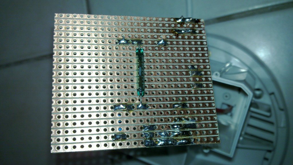
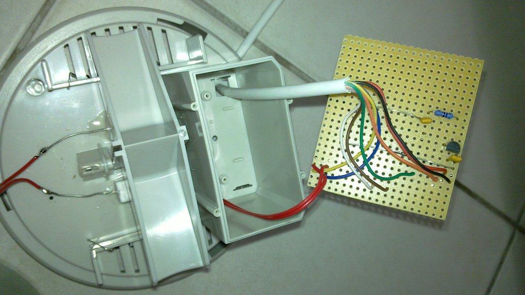
I recently added also support for the DS18B20 temperature sensor as the secondary thermometer and heated rain gauge thermometer. Note that a pullup resistor is needed for that, particularly on longer cables, the internal pullup is not sufficient. Also, 1N4148 diode clamps rather than a rtansil must be used to protect the data line of DS18B20. All this is included in the new version of the board.
UPDATE 2016: A new, slightly modified version of the PCB and firmware is available. Footprint for a SPI pressure sensor MPL115A1 has been added (software not written yet), and the board is now universal, a room thermostat can be built on the same PCB. Wireless receiver (433MHz) module has been added as well. For convenience, PDF schematics is here . The design rules of the new board version also comply with the fabrication limits of iteadstudio.com, so cheaper production in China is possible.
Weather station with a 433MHz wireless transmitter - hardware
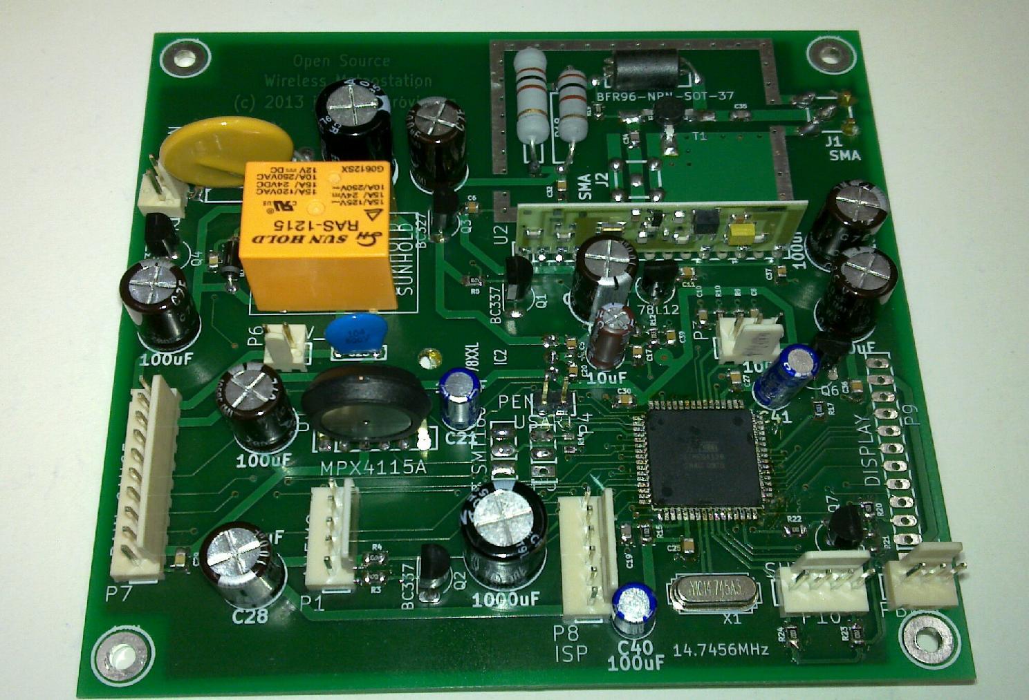
The first version of my meteostation used ATmega32 microcontroller and was hand-wired on an experimental PCB board, which was a good idea when developing and testing the circuitry. However, when building another one, I decided to design a regular PCB, since the circuitry plan was now clear and I also wanted to learn the open source CAD tool KiCad. A have also switched to SMD-mounted ATmega128 and most passive components in SMD 0805 footprints, which can still be conveniently hand-soldered. I decided to design a two-layer PCB with plated vias on a FR4 material with 1/2oz copper, which is offered at a reasonable price even in unit quantity by a prototyping service of a local PCB manufacturer in Prague.The source files for the design of this meteostation in KiCad are subject to the GPLv3 license and can be downloaded here.
The schematics in PDF format is here, bill of material is here. Note that some parts are optional - for example display, the relay to switch heating of the rain gauge, SMT160 sensor for temperature inside the rain gauge and related components, the second SMT160 sensor, or the 433MHz amplifier, which is needed only for longer distance communication - for short range you can ignore all components in the shielded box and use the first SMA connector immediately at the TX433 module. If you want to use the amplifier, notice that the shielded box should be soldered only after its functionality has been tested: use command 'T' of the firmware to send a CW signal and measure the output power with a RF milliwattmeter - something in the range 50-100mW of RF output is satisfactory (it might exceed EIRP directives for 433MHz license-free devices in some countries, though, particularly when combined with a directional antenna). Connect together both modulation inputs of the TX-SAW-433 module to achieve maximum power if needed.
If you want to make this board unmodified, you can use the gerber and excellon files. Postscript images of the layers are here.
The meteostation uses external rain gauge called TFA 47.3003, which can be purchased separately, and external anemometer a La Crosse TX20 (with serial interface, not USB version), which can be purchased as replacement part to commercial weather stations. The anemometer is used "as is" and plugged in the RJ jack. The rain gauge has to be modified as described below to work with this meteostation. The meteostation is powered by a 13.8V power supply backed up by a lead-acid accumulator, which can be shared with an alarm system (provided the cable going outside the building is fused as a protection against a short-circuit by sabotage). For the optional heating, an additional commercially available 48V/50W power supply is needed.
Here is a photo of the assembled board:
Board installed in the enclosure with sensors, developing software:
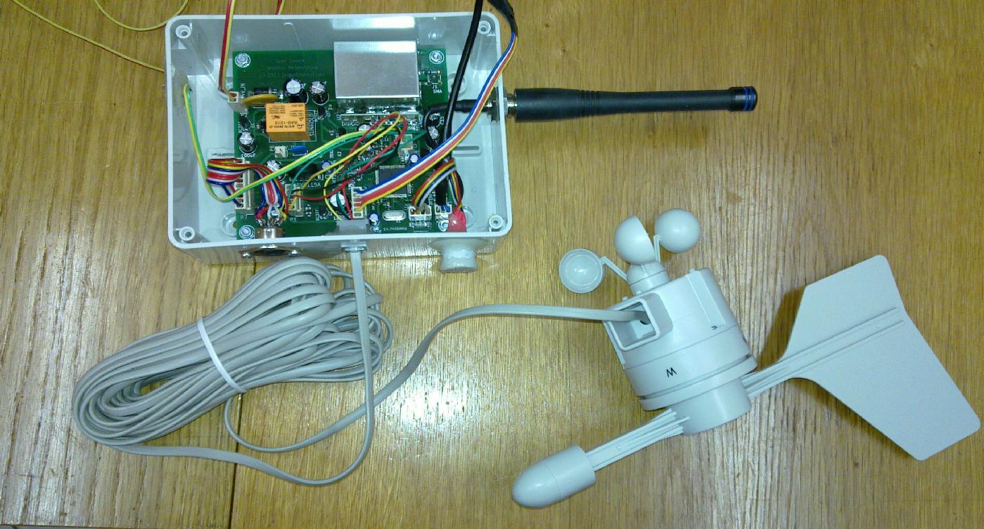
External wind and rain sensors
The meteostation has built-in pressure sensor and temperature and humidity sensor an a photo-resistor are attached to its enclosure. As a wind direction and speed sensor, TX20 anemometer in its serial bus (not USB) version is adopted without any modification. Under weather conditions like freezing rain or freezing fog, which are quite rare in my place, the sensors can freeze, but I did not find out how to make a reasonable modification to apply heating to this device. Professional heated anemometers or anemometers without moving parts are too expensive for hobby purposes. TX20 can be purchased separately as a spare part to commercial meteostations at a reasonable price. The pinout of its connection is as follows: looking into the RJ11 socket, with the latch up, pins at the bottom, counted from the left as 1,2,3,4:
1=serial output
2=VDD 5V
3= /CS (log.0 to activate the device)
4=GND
An antenna mast is a suitable place to mount the anemometer and the cable provided is reasonably long for this purpose.
The communication protocol of TX20 has been reverse engineered, so its processing is straightforward.
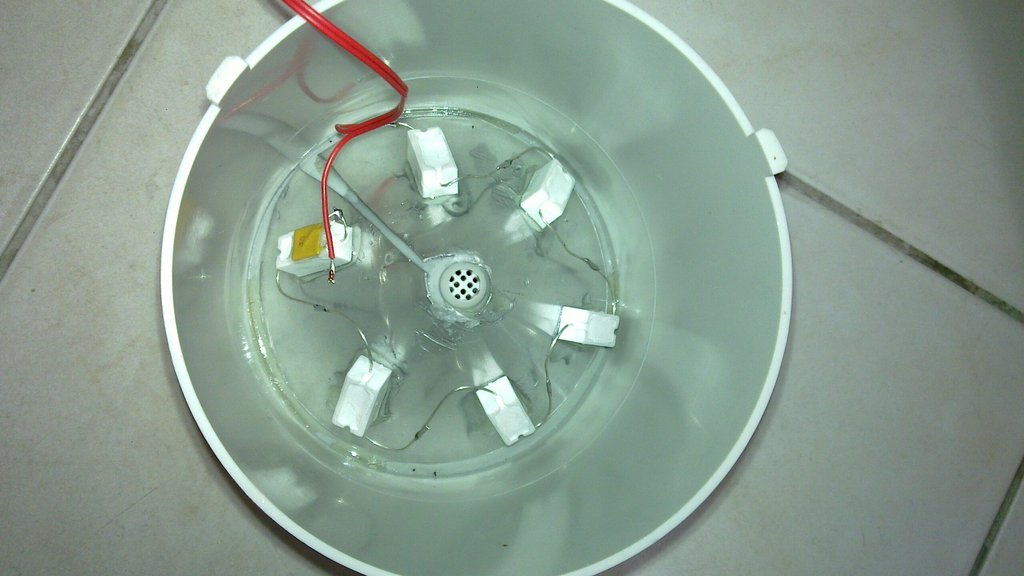
The rain gauge is more demanding concerning the mechanical work involved. As a starting point, I have found a cheap battery operated plastic rain gauge with wireless transmission. I have stripped it of the built in electronics, using only the mechanical parts. First, one has to apply heating resistors to the upper part with the funnel: to distribute the heat over the whole funnel, I have glued a cone cut and formed from 0.5mm thick aluminum plate to the bottom side of the funnel. On this aluminum plate, I have then glued six 4R7/5W resistors connected in series, and to one of them I have glued a PTC poly-switch fuse rated to 2A, connected it in series as well. This is a very important protection of the device against software bugs, since the resistors are well capable to melt the plastic rain gauge if the software temperature regulation fails and no PTC thermistor were present. (We are misusing the polyswitch a bit, so expect a reduced lifetime. I have noticed bad operation of the heating after two winter seasons and recommend thus to replace the polyswitch every second year.) A good quality heat-resistant two component epoxy glue should be used, of course. A short cable is connected to the resistors and fuse in series, which will connect to four more resistors of the same type glued to the bottom part of the rain gauge, just under the moving bucket as indicated on the photo below. The heating is powered by a 48V/50W power supply, which is switched by a relay on the main board of the meteostation.
In the waterproof electronics compartment of the rain gauge (which has been emptied of the original electronics) comes a piece of universal PCB cut to matching dimensions. On this PCB, a relay contact is soldered at the place opposite to the magnet in the moving bucket, which is connected between GND and 1k pull-up to 5V, and has a 100nF capacitor across. It is a good idea to use the relay contact salvage from the original board in the rain gauge, since it should have appropriate sensitivity. The second crucial part to be soldered there is the SMT160 temperature sensor, powered by 5V, with 100nF bypass capacitor, which provides pulse width modulated output signal. A hole for a cable is drilled into the bottom of the electronics compartment and the cable is glued there after connecting it to make it waterproof. Two wires from the cable which carry the 48V for heating go through another glued hole to the heating resistors. I hope the photos provided give enough detail.
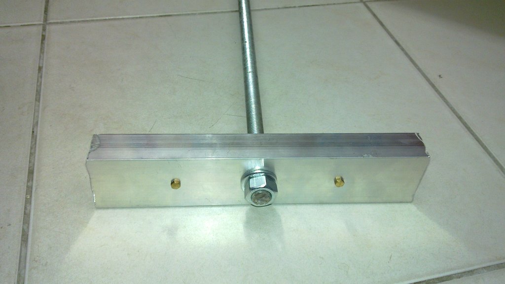
Finally, the cylindrical top part of the rain gauge should be heat insulated from outside by some suitable (waterproof) material - I have used several layers of some sort of heat insulation pad sold in outdoor shops for camping purposes. Then I have screwed the rain gauge using the factory-prepared two holes to a aluminum U-profile, which in turn was mounted to a M12 winding rod of about 50cm length. The other end of the winding rod goes through 12mm holes drilled into 2-3 concrete tiles and is tightened with two nuts; this gives the rain gauge enough mechanical stability, while it is elevated enough from the surface to have room for water exit even under winter conditions with some snow cover.
Mounting base for the rain gauge:
Heating of the funnel:
Heating of the water outlet (bottom view):
Heating of the moving bucket:
Relay contact to be placed opposite to the magnet:
The board to be placed in the waterproof compartment:
Finished rain gauge with heat insulation:
Installed rain gauge:
Update: Illuminance sensors from photoresistors seem to lack long-term stability in a continuous operation (a year or more), probably due to the influence of UV irradiation. In a new design employed in the most recently installed weather station, I have rather used the PerkinElmer photodiode VTP9812FH designed specifically as an ambient light sensor with high linearity. It's output to a shunt resistor is fed to ADC, employing also the differential ADCs with gain implemented in ATmega. Switchable shunt resistor using an additional GPIO pin is used to cover a scale of several orders of magnitude of the illuminance (0.1-10000lx). The photodiode is modeled as illuminance-dependent current source shunted by a diode and resistor, to correct for the forward diode current at voltages around 0.3V using the diode equation. However, the firmware tries to switch the shunts to keep a balance between being close to short circuit current measurement while not loosing accuracy due to being low at the ADC scale.
Weather station with a 433MHz wireless transmitter - software
The GPL licensed source code of the firmware for the AVR microcontroller in the meteostation can be downloaded here: meteo2.c, with header files meteo2.h. An additional headers backward.h and old_sfrdefs.h might be needed in some build environments.Wireless receiver and server software
To receive data from the meteostation I am using a general 433MHz ASK receiver, which handles also wireless alarm sensors and remote controls. It is based on an Aurel 433MHz RX module and Atmel microcontroller, and has been generally described here and example source code is given here.For this particular purpose, I have combined the function of receiver with a very simple burglar alarm, resulting in the code alarmchata.c with header files alarmchata.h and keeloq.c and keeloq1.c and keeloq1.h This receiver sends the data packets via UART to an embedded linux home automation server (for example Foxboard G20, or Raspberry Pi can be employed for this purpose), which among other stuff runs a daemon to log the meteostation data into files. The source code of this daemon is also free (GPL): meteoserver.c and it needs the header files above.
There runs another daemon which communicats with the GSM modem to send and receive SMS messages. This is not actually related to the meteostation, but I give the source here for completness: smsserver.c.
In 5-minute intervals, a shell script invoked by the cron daemon runs at a web server, copies the files from the embedded server and refreshes the data plots (using gnuplot). The shell script can be downloaded here and it needs a little utility collect.c.
Wireless internet connection of the meteostation
The internet connection of the meteostation was only seemingly trivial and straightforward. Since one of my meteostations is located in a rural area which is covered well only by 2G (GPRS+EDGE) network, it seemed trivial to buy just some cellular data plan from one of the available operators and a cheap USB 2G-3G stick and connect it to Raspberry Pi and use pppd. However, if a reliability of a device which has to run unattended for a long time has to be achieved, it is not so trivial. I have first bought "Archos G9 3G stick" and it was a horrible piece of junk. It was malfunctioning all the time, breaking the pppd connection frequently, in the end after every 10 seconds after connection. In Prague, with a strong UMTS signal, it seemed fine, but in the rural area, with 2G only and inside a building, it failed completely. I even suspect it was overheating due to high transmit power needed.Then I have bought "Huawei E3131" GRPS/UMTS/HSDPA stick, which has a connector for external antenna. So far, this one seems to work reliably. It provides /dev/ttyUSB0 for ppp0, /dev/ttyUSB1 which seems to be dead, and /dev/ttyUSB2 which prints a lot of service messages, but responds to AT commands as well and can be used for smsserver.
Raspberry Pi does not provide enough power at the USB port to allow reliable operation of this device. I have thus prepared a special USB cable, which takes VBUS from a separate power source, which is switchable by a P-MOSFET controlled by GPIO4 of RPI. In this way, RPI can hard-reset the modem by cycling its power if it hangs in some way.
To achieve a reliable unattended operation, it is essential to run by a cron daemon a watchdog script, which tries to re-establish the connection if it is lost. If it determines that pppd fails repeatedly, it cycles power to the modem. If even that fails repeatedly, it also reboots.
Reliability of SD card in Raspberry Pi
It turned out that another issue concerning long-term reliability was the SD card in Raspberry Pi. The use of SD card as root file system for Linux really does not match the purpose SD cards were designed for. Not only it is slow, but it turned out that the wear levelling algorithm on the card, if present at all, does not match the requirements of a root file system device. After 1/2 year of continuous run, I have observed frequent file system corruptions and in the end a total crash - even using a decent Kingston card.I would thus recommend to anybody who intends to run Raspberry Pi in 24/7 high availability mode to make just one FAT partition for /boot on the sdcard and change the cmdline.txt to boot with a root file system on a SATA SSD disk attached via USB/SATA adaptor. (Kernel has to include USB storage driver, of course). It will be much faster and (hopefully) much more reliable.
From my other constructions, you might be interested in an ESR meter based on ATmega8, again with free source code, Wattmeter and power factor meter, again with free source code, or in a micro spot welder.
My Electronics page
My hobby page
My main page with e-mail contact
TOP of my family pages