Open hardware/open source home automation and alarm switchboard based on Raspberry Pi and ATmega128
Update 2021: A new respin of the board with LPC1115 microcontroller, LAN, GSM, and RFM22B transceiver, and footprint for RPI4 has been developed rpialarm_v2.pdf and rpialarm_v2.zip. New firmware will be published when finished.
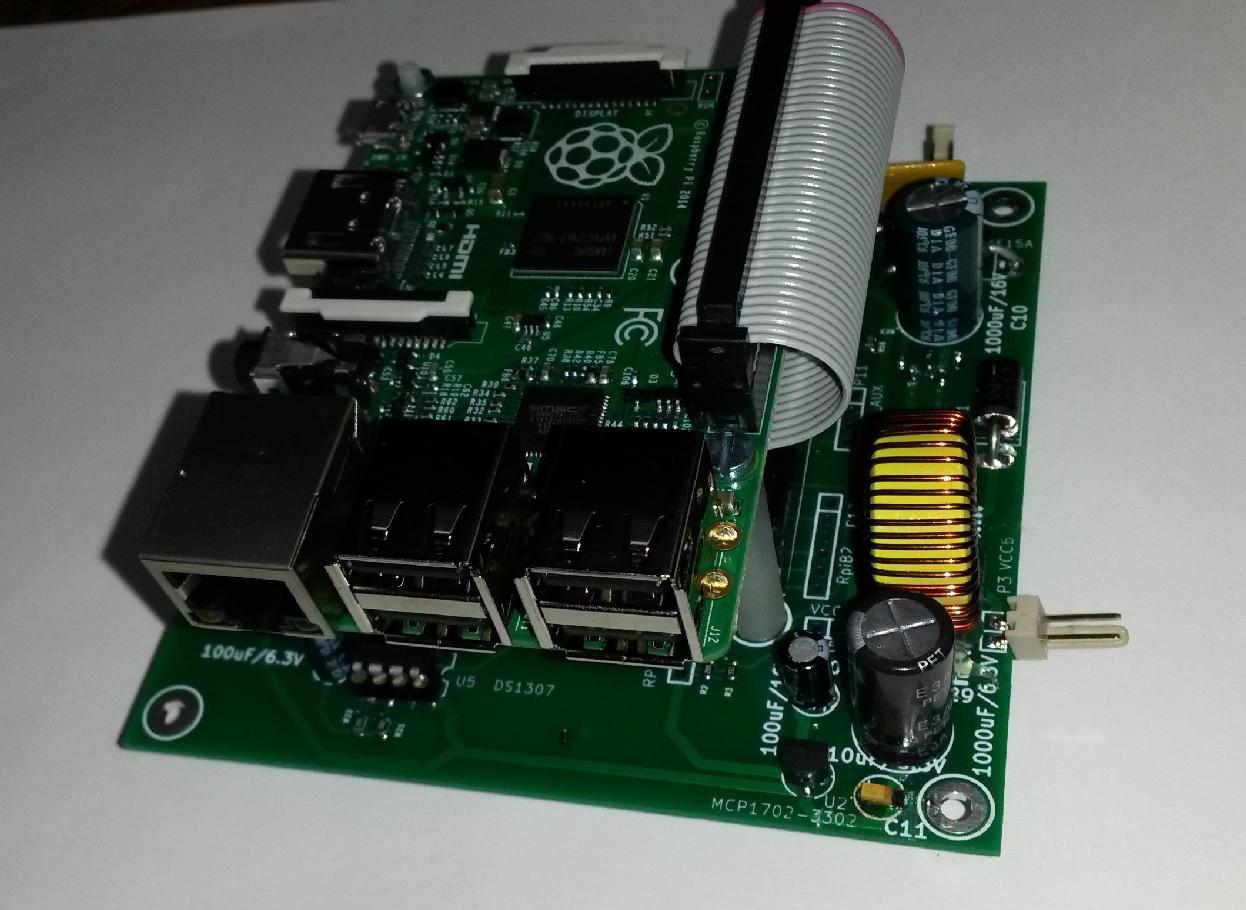
The aim of this project was to develop a home server based on the Raspberry Pi, which would encompass the functions of burglar alarm and home automation central and be flexible and extensible. It also logs data from a wireless meteostation and periodically sends them to a public web server. For this purpose, I have designed a PCB board where RPi is mounted onto as a daughter-board, while the low-level electronics of the main board is controlled by ATmega128. The main board has the following features:0. 5V power for RPi, switchable via P-MOS (ATmega watchdogs RPi)
1. I2C real time clock for RPi.
2. second serial port (TTYMAX) with RS232 interface for RPi
3. two channel PWM generator
4. Wireless 433MHz interface, based either on RFM22B module (software not prepared yet), or on Aurel ASK modules, with an amplifier and antenna switch
5. Adjustable DC/DC converter for external devices
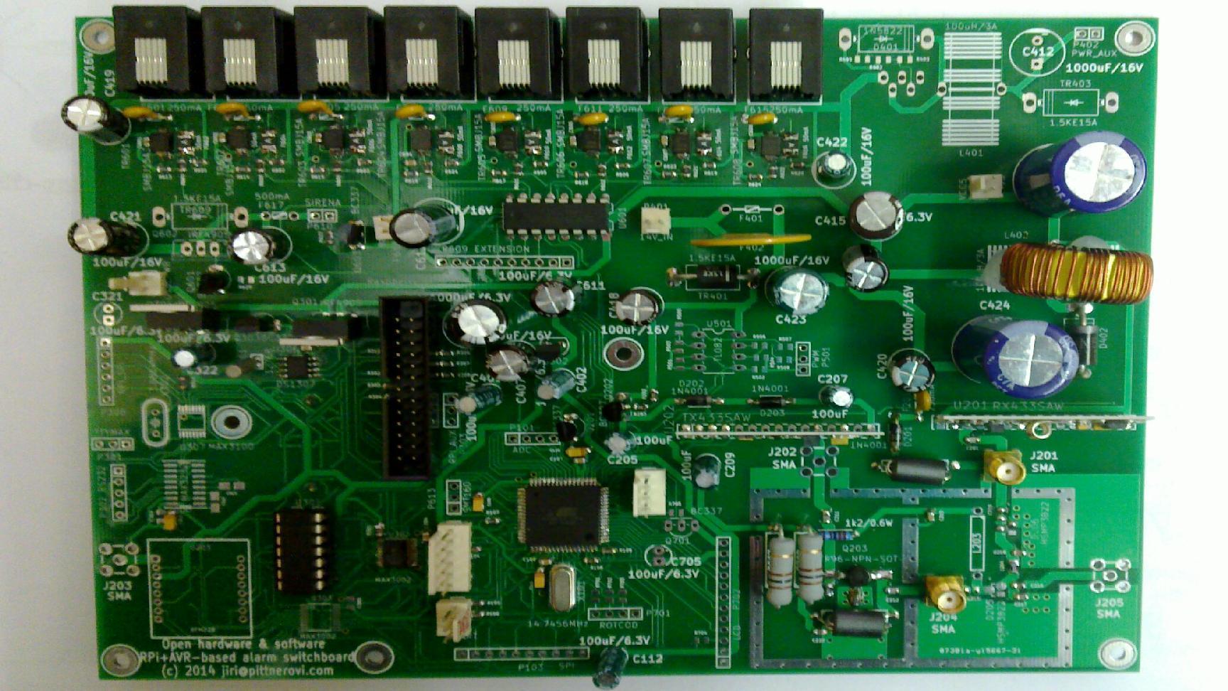
6. 8 sockets for external PIR or other sensors, each providing 13.8V/250mA PTC fused power and "balanced loop" input (transil and PTC fuse protected) with 4 distinguishable states (normal, activated, interrupted, short-circuited) A connector for external daughter-boards to expand up to 32 wired alarm sensors is provided.
7. RGB LED output, beeper output, sirene power output
8. optional alphanumeric LCD display and rotational coder for direct user interaction with the ATmega firmware
9. 5V power switchable via P-MOS, to ba able to watchdog an external GPRS/UMTS modem, using a modified USB extension cable
10. hardware interface for in-system-programming of ATmega by a program running on RPi, for remote and comfortable firmware upgrade
11. Two mounting holes matching the new RPi board dimensions are provided, so it can be firmly mounted.
The software running on ATmega takes care of low-level stuff, like the (de)modulation of wireless communication on 433MHz band, scans the alarm circuits etc. The higher layer of software runs on RPi, which logs all events, send SMS/email in case of alarm, receives data from thermometers, meteostation, and wireless alarm sensors, and controls collaborating devices like locks, relays and thermostats. It can also interact with IP security cameras via an external script. A simple encrypted wireless protocol for reliable, authenticated and encrypted communication with the underlying devices has been developed. Its simplicity allows the end-point devices to be extremely simple, based just on an 8-bit AVR MCU and an ASK wireless module. Notice: The rolling code scheme employed supports 32-bit counters to prevent a reply attack exploiting the keeloq-style resynchronization scheme. However, for backward compatibility it supports also 16-bit counters, if the transmitted messages are not flagged by the LONGCOUNTER bit (see source keeloq2.c). The human-operated devices not supposed to transmit more than 32768-times can work in the backward compatible mode, while devices transmitting automatically should use long counters.
The board is powered by 13.8V from a modified PC power supply backed up by a lead-acid battery. On-board switched mode DC/DC converters generate other voltages. PTC fuse and transil protect the circuitry from overvoltage or bad polarity. There is a 5V outlet suitable to power a SSD disc.
Page is under construction, more information will follow.
Hardware
For convenience, the complete schematics in available as a PDF file. All KiCad design files and Gerber files for production are open hardware under the GPU GPLv3 license and are in a zip archive.Note: do not replace TXS0108 by MAX3002, I tried it and they were not working reliably. Also note that TXS0108 is designed to drive CMOS inputs and its driving capability is rather weak due to its bidirectional property. It might not work reliably if some USB/USART cable etc. is connected to it instead of the Atmel MCU (as RPi console for debugging). Therefore an optional 74LS00 has been added (as a quick patch in a board respin) to make more powerfully driven USART at 5V.
Note: the antenna RX/TX switch is experimental, footprints for the lambda/4 transmission line "emulation" from lumped elements are provided as well as through holes to solder a piece of RG174 coax
I have also designed a simpler board omitting the alarm features and ready for the new RPi Model B or RPi2. Schematics is rpiatmel.pdf and all Kicad design files are here rpiatmel.zip.
Simple RPi support board
AVR firmware for the ATmega128
The firmware for ATmega128 is open source under the GNU GPLv3 license: rpialarm.c. In some AVR development environments, you might need header files backward.h and old_sfrdefs.h. The firmware is programmed to ATmega from the RPi, using bit-banging on its GPIO. For this, install my modified version of the UISP program.Note that you have to appropriately change #ifdefs for 1st and 2nd release of RPI, since GPIO 21 was swapped for GPIO 27 in the new version of RPi. (Btw. in the new RPI real time clock is on i2c rather than on i2c0.)
Most parts of the board have been tested, and the device is in continuous operation since spring 2014; see the empty footprints on the picture below for exceptions.
Software for the Raspberry Pi
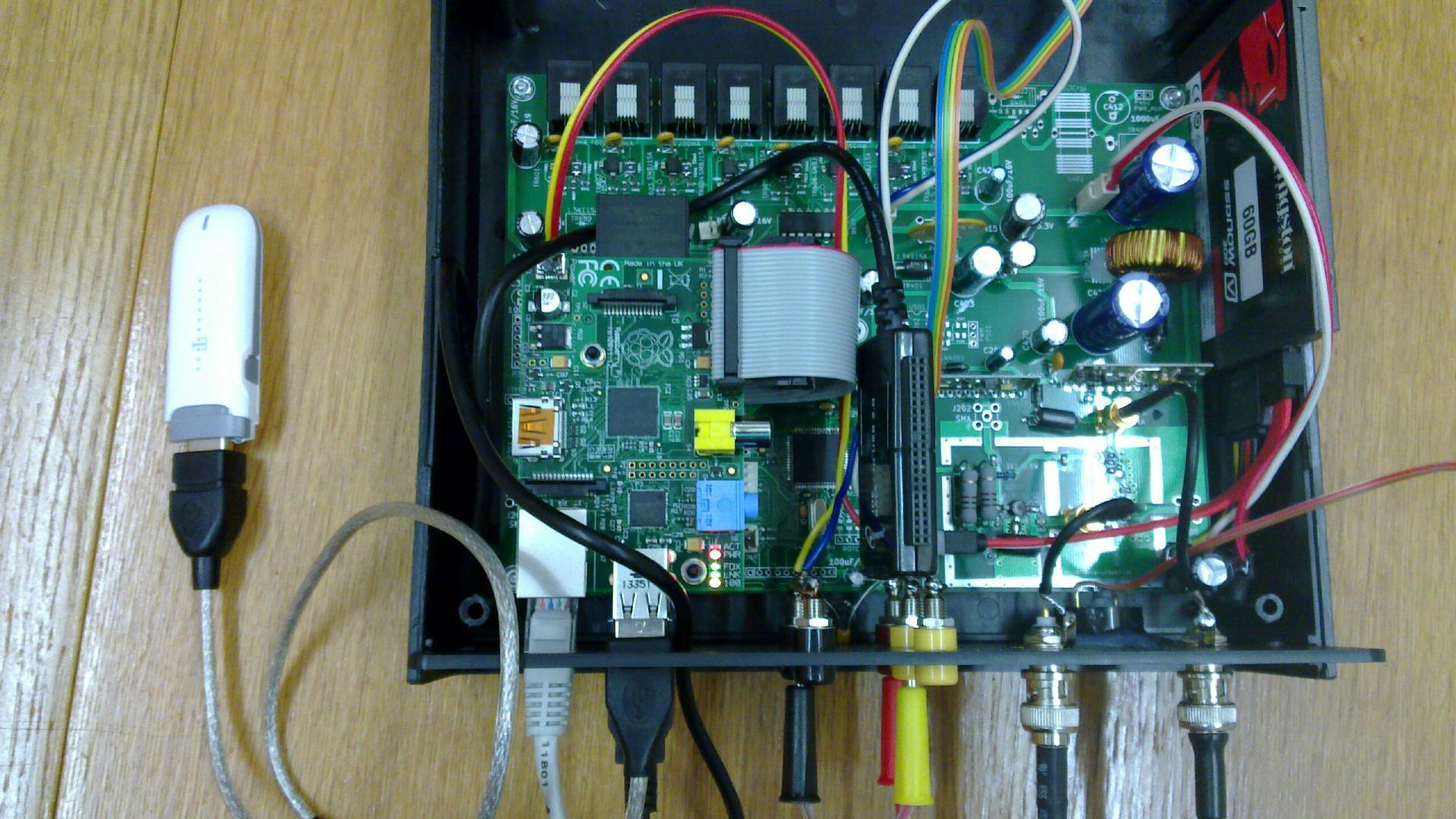
RPi can run your favorite linux distribution, just make sure that ttyAMA0 is not used as console and there is no getty running on it, since it is used to communicate with the ATmega128 processor. On top of the OS, you run alarmserver daemon to communicate with ATmega and smsserver daemon to communicate with GSM/UMTS modem for sending and receiving SMS. This software I distribute under the GNU GPLv3 license, in a zip file rpi_daemons.zip. All encryption keys and local configuration is done in the generic_keys.h header file, which you can also rename to location_keys.h and change #define LOCATION appropriately.Assembled board
Assembled device in an open enclosure - with Raspberry Pi board and SSD disc, USB/SATA adapter and USB UMTS/GPRS modem.
Reliability of SD card in Raspberry Pi
It turned out that another issue concerning long-term reliability was the SD card in Raspberry Pi. The use of SD card as root file system for Linux really does not match the purpose SD cards were designed for. Not only it is slow, but it turned out that the wear leveling algorithm on the card, if present at all, does not match the requirements of a root file system device. After 1/2 year of continuous run, I have observed frequent file system corruption and in the end a total crash - even using a decent Kingston card.I would thus recommend to anybody who intends to run Raspberry Pi in 24/7 high availability mode to make just one FAT partition for /boot on the sdcard and change the cmdline.txt to boot with a root file system on a SATA SSD disk attached via USB/SATA adaptor. (Kernel has to include USB storage driver, of course). It will be much faster and (hopefully) much more reliable.
Devices collaborating with this device:
Wireless thermostat
Wireless thermometer
Wirelessly controlled electromotoric lock
Wireless meteostation
Back to:
My Electronics page
My hobby page
My main page with e-mail contact
TOP of my family pages