Digital wattmeter, power factor meter and impedance meter, and power analyzer with a Bluetooth connection to a software datalogger and oscilloscope display (Wattscope)
Hobby construction based on ATmega64 with a GPL open source firmware
In order to choose an inverter or portable electric generator powerful enough to supply a given electric tool or appliance, it is not appropriate to just look at the nominal power consumption of the tool. First, the inverter/generator has to be dimensioned for the apparent power consumed by the device, which can be substantially higher then the real power consumption. Second, the device can behave non-linearly, for example switching power supplies for computers without power factor correction circuit draw strongly anharmonic current from the mains. Third, electric engines typically have much higher power consumption (both apparent and real) due to the current surge in the fraction of second when started. It is also useful to be able to determine anharmonicity of the electric mains (or output of a power inverter), the device described below can act also as a simple power quality analyzer. To measure these quantities was the motivation for development of a wattmeter with an oscilloscope-like display of one period of the mains voltage, current, and power, with a capability to measure the start-up current, as well as with a data-logger described below, for which I invented the word "Wattscope". Simple wattmeters targeted to checking just the power consumption of appliances available on the consumer market cannot do this, while professional instruments like power quality analyzers are far too expensive.
When deciding which MCU to use, I thought that ATmega32 would do. However, it turned out that the size of floating point library was a bit too large, and also ATmega32 at 16MHz would be a bit too slow. So I swapped it for ATmega644-20PU over-clocked to 24MHz, which seems to work reliably. However, if I would build it again, I would use perhaps some ATxmega, which offers simultaneous ADC operation and higher precision, simplifying the data processing. Or even better would be to use the STM32F4 Discovery kit, which is sold very cheaply, and that ARM Cortex 4 CPU has hardware floating points and DMA-able ADC channels, so it would be ideal for this application. Setting up a linux-based development environment for STM32F4 is not difficult. Possibly even better would be some of the STM32F3 MCUs, which have 16-bit sigma/delta ADCs fast enough for this purpose. I would also reconsider the choice of the instrumentation amplifier, switching definitely to the more modern AD8253, with which I had much better experience when building a milliohmmeter. So take the remainder of this rather as a starting point for a new design offering better accuracy, rather than a definitely recommended one. Nevertheless, the wattmeter works well and is good enough for the intended purposes.
I have constructed the device on a universal prototyping board, and for the above reasons I will not design a PCB for it, or even draw schematics in Eagle. I have captured the schematics by hand and scanned it to a PDF file here. Only the non-trivial analog circuitry is captured there, I have omitted the obvious things like connecting the display to MCU etc. The pinout for these connections is just noted in the firmware source code (GPL licensed). It needs an additional header file atmega168compat.h. Basically, I am using the PGA202 programmable gain instrumentation amplifier, LT1014 for additional gain x2 and x5 stages and for creating 1.28V reference from splitting the internal 2.56V reference of ATmega. Furthermore, I am using the I2C-controlled digital potentiometers DS1803-050 for offset calibration of the PGA202, which has to be done separately for each gain range. Concerning the software processing, the basic measurement is interrupt-driven, with conversions triggered by a timer. Only integer operations are used in the real-time interrupt routine to accumulate necessary data, processing and printing is done in an endless while loop of the main code. I am using a circular buffer to time-shift current samples by a quarter of period to compute not only cos(phi) but also sin(phi) and thus determine correct sign of the reactive component and get phi more accurately. Another interesting point is perhaps the compensation for an additional phase shift due to the interleaved sampling of voltage and current. Using STM32F4 mentioned above would allow enhanced precision (12-bit ADC and higher sampling rate), simultaneous ADC sampling would avoid the necessity for the phase shift compensation, and also it would have CPU power to do real-time FFT to better characterize the anharmonicity. Unfortunately I do not have time to redesign the wattmeter with the ARM CPU.
Notice that due to tolerances of resistors etc., after building it, you should calibrate the device against a good quality multimeter. In the source code appropriate places to change constants according to the calibration results are commented.
To power the device I have used PCB with a 220/110 -> 5V SMPS from an old cell phone charger, so the device can operate on both US and EU mains. Sampling frequency is chosen also in such a way to support both 50 and 60 Hz. The resistors to sense current should be adapted if higher currents are needed in the 110V mains. Present design supports 16A, which is the most common circuit breaker value for 1-phase wall outlets. Note also, that high quality resistor should be used - when it burns, it takes the whole device to the hell, since mains voltage will go straight to the ADC and CPU. (I have put some transil diode protection there, but if the circuit breaker on the mains is not fast enough, even that might not help.).
Important security note: the device is galvanically connected to mains - only experienced persons should build it. Particularly, it is necessary to guarantee that the digital GND will not be connected to the live wire of mains - the mains voltage would go to the display shield and to the serial interface connector, causing quite some damage. USE POLARIZED MAINS PLUGS to guarantee which is the live wire - how to do it varies with country.
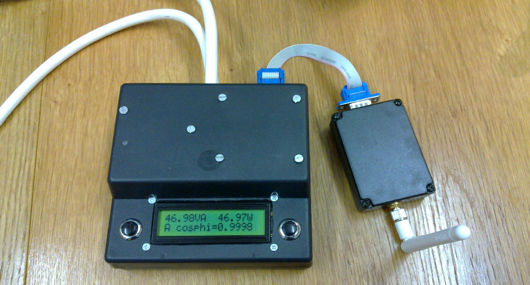
Operation of the wattmeter is controlled by two pushbuttons left and right from the display. In the default operation mode, left button toggles measurement ranges 0-9 and auto-ranging "A", while right button rotates through the list of measured quantities (true and apparent power, power factor, voltage and current, maximum voltage and current, consumed energy, anharmonicity, impedance and equivalent serial inductance/capacitance etc.) In menu mode, which is selected by pressing left button while "MENU" was chosen previously by the right button, you can select various operating options including sampling rate and number of samples. Besides menu, there are shorthands for two frequent operations: Recalibration of zero can be invoked by pressing left button while holding right one. Software auto-zeroing is toggled on/off by pressing right button while holding left one. (You need to switch off software auto-zeroing for asymmetric loads which use a diode in lower power mode.) Alternatively it can be controlled remotely via the USART console (for list of commands see the source code).
In spite of the simple design, the wattmeter covers more than 4 orders of magnitude, starting in tens of milliwatt and going up to 3.5kilowatt. At the lower ranges, apparent power, phi and impedance becomes pretty inaccurate, but real power still has better noise cancellation properties. Definitely it should be accurate enough to check the power consumption of devices in the whole range from cell phone chargers up to high-end electric chain saw.
By the way, an excellent (relative) precision is obtainable also for the (real-valued) resistance readings: I was able to measure resistance of a kitchen cooker rated to 1500W at 230V to four digit accuracy 35.xx ohm and got even quite a smooth curve of the temperature dependence of its resistance, which was in the order of 0.01 ohm per 10 degrees Celsius. This brought me to the idea of using the heating element itself as a thermistor to implement a temperature control and use such an extremely cheap cooker as temperature-regulated bottom preheater for SMD soldering. However, I had no time to develop it further, as it is often sufficient to operate the cooker at low power with a simple triac regulator without feedback and heat it to roughly 100 Celsius to get a reasonable bottom pre-heating for simple work.
To achieve comfortable (wireless) data-logging (with a galvanic isolation for safety as a side effect), I used the ConnectBlue OBS410 Bluetooth module, connected and configured according to its datasheet. Since it is not exactly cheap, I have built it into a separate enclosure to be used also with other devices as an external module, rather than to have one dedicated to the wattmeter. This module is of course optional, the wattmeter itself will work standalone as well.
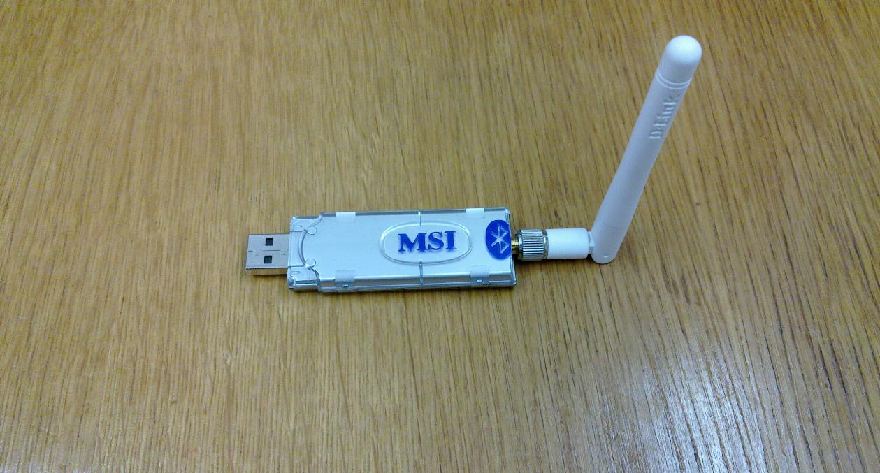
At the PC's side, the built-in Bluetooth has a rather poor antenna, so I took a USB MSI Bluetooth stick, removed the built-in tiny chip antenna and soldered an RSMA connector to it. This gave me a range over 10m and through 2 walls. It might violate some EMI regulations, though.
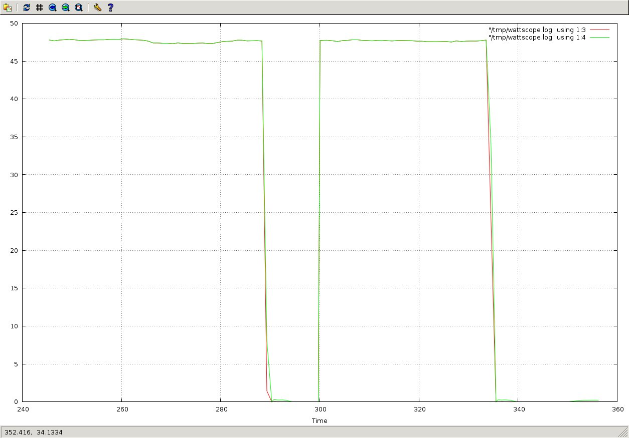
To use the data-logger, first configure and pair the Bluetooth serial port to, say, /dev/rfcomm6 (details depend on your Linux distro and desktop environment). Use Bluetooth channel 1. Compile and install my wattscope utility from the GPL-licensed source code. You also need the Gnuplot program installed. Then run the following command to display real and apparent power as function of time:
wattscope -y 3 -y 4 < /dev/rfcomm6
To start the data-logger window, execute 'echo P > /dev/rfcomm6' in another window. To start the scope window, execute 'echo O > /dev/rfcomm6'. Both can run simultaneously. The measured quantities are also logged to /tmp/wattscope.log
Here are the screenshots:
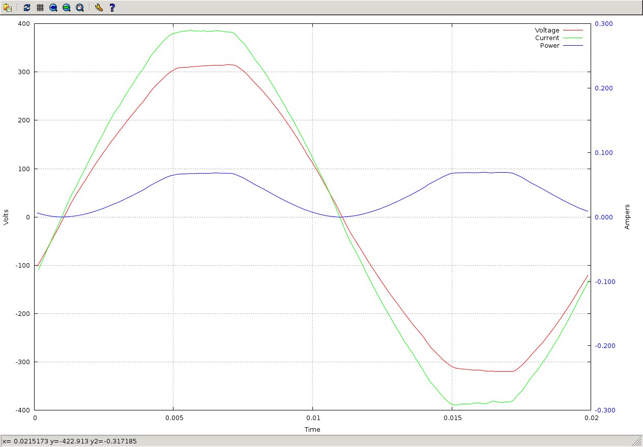
Yes, we have that much deformed sine wave on the mains in Prague due to switching mode power supplies, I checked it with a good oscilloscope!
From my other constructions, you might be interested in an ESR meter based on ATmega8, again with free source code, or in a micro spot welder, suitable for example for making accu battery packs.
My Electronics page
My hobby page
My main page with e-mail contact
TOP of my family pages