How to build a capacitor-discharge micro spot-welder (do-it-yourself hobby construction with open source firmware)
A device which can be useful for various hobbyists is a micro spot-welder, powered by a large capacitor discharge. Professional devices of this kind (Powerstream, MTI Microwelding, Spotco, MacGregor etc.) are pretty expensive, so here a home-brew construction makes sense if you like e.g. to refurbish battery packs yourself.
Resistance spot welding might seem trivial on the superficial first view, however, I can only advice you to forget simple constructions based on a thyristor, which you might find on the internet. The timing of the pulse(s) is essential to get good and reproducible results. If you dump all the capacitor energy at once via a thyristor, either it will be too little and the joint will not be robust enough, or too much and you will burn a hole through the material (and possibly become burnt by drops of liquid metal :-)). On the other hand, for hobby purposes certainly one does not need the precise pulse shaping offered by high-end professional devices, so the following construction seems to me to be a reasonable compromise between simplicity and cost versus functionality.
I have found a nice construction on the internet, however, it was controlled by a PIC micro-controller, while I prefer to work with Atmel, due to the GCC support for this architecture.
Note: this website was offline for quite some time, so for your convenience I give here the schematics and bill of material of the Ultrakeet's spot welder, which I downloaded from there. However, notice also that for a new construction some improvements should be done in the power part, cf. the notes below and on the pages of other people who were developing similar welders which are linked from here.
In my construction, I have essentially copied the power part of the above project, with the following minor changes listed below (I even did not draw a new schematics and used a universal prototyping PCB to build the device):
Instead of a car hi-fi capacitor, I used 20 pieces of 47000uF/35V in parallel to be able to go to higher voltage, having about 600 Joules of energy available for a more heavy duty work. Capacitors are protected by a Zener diode against accidental overvoltage (they are not cheap!) and a 2kohm bleeding resistor discharges them slowly when not in operation. I added a resistor 1k/1W across the electrodes to have source terminals of the fets at a defined potential when the welding electrode is disconnected.
I have used 6 IRFP2907 in parallel rather than 4 ones to handle the current.
I power the device from a laboratory power supply, since the box was so full of capacitors and heat sinks, leaving no space for its own power supply. 3A are enough for welding, cutting with repetitive pulses would need more. Control circuits have an extra 10000uF capacitor after a diode to bridge over periods of lower input voltage due to high load of the power supply when charging the main cap.
5V for the logic are obtained using LM2575-5 connected according to the data sheet.
Atmel ATmega16, timed by a crystal (with accordingly programmed fuse bits), with a 100nF bypass capacitor is used to control the unit and show the status on the display.
On the back panel (invisible on the photo) is a connector for ISP programming and TTL-level RS232 - a trivial thing, but pretty convenient when developing the firmware.
Rotational coder uses Atmel interrupt pins, potentiometers are connected to A/D converter pins (cf. comments in the source code).
Electrodes are made from 8mm diameter copper rods, sharpened at one end, insulated by a heat shrink tubing, with a M8 winding cut at the other end. They are screwed into hat-shaped brass nuts, to which 6mm diameter cables are soldered, and tightened with another M8 nut.
High-current connections inside the device are made from a 6mm diameter copper wire, doubled where mechanically possible.
Material cost for the construction should be around USD 300 (and can still be reduced if you use lower voltage capacitors - 12V is enough for battery pack welding), an order of magnitude lower than the price of a low-end professional device.
The result can be seen below and here you can download the
open source code firmware for the micro spot welder with ATMega micro-controller
published under the GPLv3 license. In the source code, connections of ATmega pins to the control and power parts are listed.Depending on the version of avr-gcc and headers you might need the header backward.h
If you just want to build it without cross-compiling the source, here are the hex files for ATMega16 and ATMega32. NEW: Somebody asked me for a hex with a longer duration of the second pulse, it is here for ATMega16 . External crystal 14.7456MHz is assumed, so do not forget also to program the fuse bits appropriately (I used fuse_l=0x2f and fuse_h=0xf9).
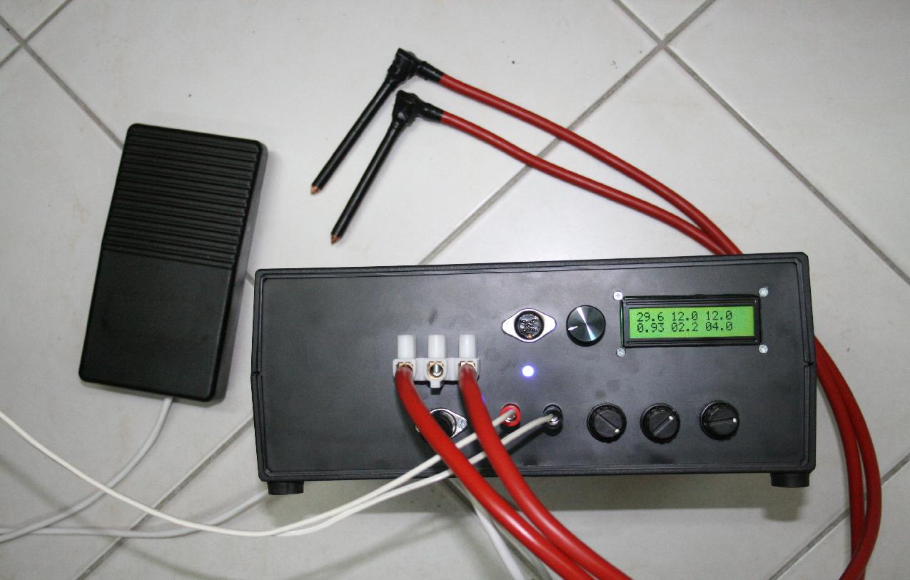
The numbers on the display are external power supply voltage, target voltage, current capacitor voltage at the first line; time of first pulse, delay between pulses, time of second pulse in milliseconds at the second line.
Rotational coder with a push switch selects capacitor voltage (and in future firmware switching between various operation modes via a menu can be easily implemented), the three potentiometers define the timing. After triggering, actual pulse energies (including losses on internal resistances) are computed and displayed until the trigger pedal is released.
Photos of the inside and details of the electrodes are here.
Tips for battery pack micro spot welding using this home-made device:
Use 0.075 to 0.12 mm thick stainless steel strips. The nickel ones recommended for this purpose may be difficult to get locally and overseas postage would cost at least double the price of the material ... After a lot of search I have found stainless steel sheets of appropriate thickness produced by www.ksmetals.com in a local shop for hobby modelers. Strips can be cut from this material easily.
Make the electrodes really sharp and press them firmly to the connecting strip lying on top of the battery cell.
For 0.075mm thickness, 6 Volts and 0.5ms first pulse, 2ms delay, 4ms second pulse worked best for me. It may, of course, differ, depending on what internal resistance of the welder you happen to achieve in your construction.
Schematics and printed circuit board for the spot welder
Recently (2010) a colleague from UK has built a similar device, and agreed to publish his schematics and PCB design here. You can download a PDF file, or Altium designer SCHDOC file and PCB file. (If anybody knows how to convert from Altium designer format to Eagle, please let me know.) This design is slightly different from my construction (mainly by the power supply), but should be fully compatible with my firmware. The PCB has, however, not been tested. He also suggested an improvement of the design of the power part, placing the discharge and weld fets on the lower side of the load (source to GND, drain to one electrode, other electrode to Vcap) and using a P-channel FET for charging the Cap.
Another schematics (in Eagle) has been contributed by Franz (Tauchsport-Tschur at web.de), you can download it here; it should be compatible with my firmware.
In november 2011 Tim O'Brien published at his web page a CD welder construction inspired among others by this design. He proposed also some improvements, among others a better way of driving the MOSFET gates in order to lower power dissipation and allow for shorter and more precisely controlled pulses. Particularly useful is his experience concerning car capacitors by several manufacturers, which often sell product of much inferior quality than advertised. His page is very detailed, contains a lot of useful information and is definitely worth reading if you consider doing a similar project.
In 2012, a spot welder construction inspired by this design was published by Radu Motisan at his web page and also presented at hackaday.com. He published schematics and PCB design, has rewritten my original firmware to C++ and implemented the cutting operation mode. See also the article here.
Also, if you are interested in a more heavy duty work than capacitor-based device can handle, a transformer-based spot welder is the best choice. A very interesting modification of an old handheld spot welder of GDR production by Henrik Haftmann, who added control electronics based on ATtiny can be found here (in German language), including open source schematics and firmware source code.
In 2014, Georgi Belev built a welder based on this firmware and published a nice video of its operation on youtube.
From my other constructions, you might be interested in a logging wattmeter with bluetooth, based on ATmega64 or milliohm/ESR meter based on STM32F373 MCU or a simpler ESR bridge based on ATmega8 to check the quality of capacitors, both with free source code.
Back to my electronics page
Back to my hobby page
My main page with e-mail contact
TOP