An experimental open hardware and open source avionics (AHRS IMU sensor), possibly useful as a standby attitude/heading indicator in ultralight planes
As I recently obtained a Czech ULL(A) pilot license (roughly similar to light sport aircraft license in the USA), I became also interested in hardware and software for avionics and navigation. For navigation purposes, the hardware of choice is clearly a tablet or smartphone with GPS, and a lot of software exists, mostly with a yearly subscription fee, but I found also two free and open source Android apps Cumulus and AVARE (this one has USA and Canada maps only).State of the art in attitude and heading reference systems and inertial measurement units for small GA, LSA and untralight planes
Concerning the avionics, some LSA-category planes have already full-featured glass cockpit, e.g. Garmin G1000, but some have rather spartan equipment - the plane I am training on has a classical instrument panel and no gyroscopic instruments (as neither IFR nor night VFR are allowed in this plane category anyway). The most interesting and difficult sensor for the glass cockpit is clearly the attitude and heading reference system (AHRS). Two types are presently in use: ring laser interferometers (RLG) and microscopic vibration structure (MEMS) gyroscopes.. Example of the former is Honeywell GG1320, MEMS based FAA certified gyro for general aviation is Memsic's AHRS500GA, and Garmin has its own unit GRS77/GMU44. Recently SiliconSensing offered an accurate IMU (inertial measurement unit) DMU30 (0.1 degree/hour drift). Analog devices IMUs like ADIS16495 are also very accurate. Modern MEMS IMUs with better than 1 degree/hour GYRO stability are also provided by VECTORNAV. This is good enough accuracy for AHRS, but not enough for intertial navigation, where at most 0.01 degree/hour is required. That high accuracy is presently provided only by the ring lasers or fibre optic laser gyroscopes.Another advantage of RLG is that they are completely insensitive to accelerations, while MEMS devices generally crosscouple acceleration and rotation. The only disadvantage of RLG is the price, which is too high even for smaller GA planes, not to speak about ultralights. An older overview of inertial navigation sensors is available here , more recent and excellent text on this topic is in the book "Introduction to Avionics Systems" by R.P.G. Collinson.
In early 2019, a relatively inexpensive multifunction device AV20 developed by AeroVonics became FAA-certified as a Non Required Safety Enhancing Equipment (NORSEE) instrument. It includes the attitude indicator and obviously must use MEMS sensors.
By the way, one interesting feature of this device is a "probeless" angle of attack indicator. The principle is described here. The principle is basically that aircraft pitch and g-load is measured by MEMS anyway, and vector of relative wind is obtained from accurate airspeed and vertical speed measurements. Actually it is not a new idea, it has been patented in 1972, cf. here and here.
In view of the fact that this "software" AoA measurement has been known for decades, I really do not comprehend why this principle is not used in multi-million-dollar machines like the unfortunate Boeing 737 MAX 8, at least as a check whether hardware AoA sensor output is sane. The sad story of the two 737 MAX crashes, if what has been reported in the media is true, revealed an incredible incompetence of the firmware developers or their managers at Boeing. The MCAS device used input of only one AoA sensor, ignored the other (AoA disagree signalling was optional), pilots could not manually override it and recover from the resulting nose-down attitude and the results were disastrous.
Why the hell did the firmware not deactivate the device completely if the AoA sensors disagreed grossly? Or why this software AoA determination was not employed to decide which of the two hardware AoA sensors is the broken one?
Back from this AoA detour to the main topic now. Both ring laser and MEMS sensor classes yield angular velocity, which has to be integrated in time to get the orientation, which the old mechanical gyroscope provided directly. And any systematic error in the angular velocities will accumulate during the integration, making the result useless, if not accurately corrected for.
As a side note, it is interesting that the mammal vestibular system is also a 6-axis sensor yielding linear accelerations and angular velocities and it suffers from the same problem, since the evolution developed it for movements at the ground. Under normal circumstances and during VFR flight, the brain corrects the felt attitude by observing the natural horizon. This is why pilots need an attitude indicator in the first place and why the flight in instrumental meteorologic conditions (IMC) without proper instruments and training ends very often by spatial disorientation and collision with terrain. On the other hand, birds have in addition to the (possibly more accurate) vestibular system also a baroreception sensor in their inner ear and they are also able to "see" the magnitic field, having thus a "9-axis" sensor.
Why android orientation applications for "artificial horizons" or "primary flight displays" typically do not really work
All the certified and commercial AHRS and IMU systems are pretty expensive, on the other hand there are now available many very cheap MEMS chips combining gyroscopes, accelerometers, and magnetometers ("9-axis sensors") like Bosch BNO055 or Invensense MPU9250. They are used in many commercial applications, typically smartphones and tablets, but also in drones. However, a question is whether sufficient accuracy can be achieved using these parts, to be of any use for aviation purposes. For example, BNO055 has a "fusion mode", where a manufacturer's black box algorithm combines inputs of all sensors to yield orientation results. However, this algorithm might have been designed with ground applications in mind and when subject to a prolonged mild coordinated turn in flight, it could confuse the resultant of gravity and centrifugal force for gravity and yield false results. Many of the "artificial horizon" Android apps are graphically nice useless toys exactly due to this problem (or possibly they even run on devices with accelerometers only and still pretend to have a gyro!) - at least you can see often in the reviews such reports. Maybe some are better, at least claim to use better fusion algorithms; I could not test the ixGyro application, since it requires Android 4.4 and I have 4.2 and will not upgrade it just for this purpose. But this app is rather expensive and still it has mixed reviews and possibly it runs well on some phones and poorly on other ones. Basically, in Android the gravity is separated from other accelerations by a low pass filter (!)", which is quite OK for ground applications but absolutely wrong for aeronautical purposes. Unfortunately, the misuse of the name "gravity" instead of "low frequency acceleration" is highly misleading and the "rotation vector" from the android sensor (which is actually inot a vecotr but a quaternion!) is wrong for the above reason. Obviously the author of that API was neither physicist, not a pilot, and never tried to take his smartphone to a merry-go-round or a similar fairground attraction. Every smartphone app which uses this standard library approach is doomed to fail. One has to subtract the accerations due to non-intertial motion obtained from an independent source like GPS to obtain the real gravity vector. This correction contains linear acceleration and even more importantly the vector product of linear and angular velocity (more detail will be given below in the description of the AHRS algorithm). The deeper reason for this comes from Einstein's general relativity, which tells us that gravity is locally indistinguashable from acceleration and obviously thus cannot be filtered out by lowpassing the accelerations.
If you are android developer with interest in this application and happen to read this, you can use my open source code for the AHRS provided herei, rewrite it to java and Android sensor API. I am myself not really interested in coding GUIs and smartphone applications to do this.
Design objectives for the experimental open hardware/software DIY avionics
I thus thought that it would be interesting to get some hands-on experience in this direction, trying a few of the cheap MEMS chips, available also as inexpensive modules from Aliexpress. Ideally, when sufficient accuracy would be achieved, a construction of inexpensive open hardware/open source usable experimental avionics would be possible. The barometric and other sensors are relatively trivial, compared to achieving an accurate IMU. The prices of aviation-grade IMUs indicate that there should be rather non-trivial know-how involved in their construction and calibration. However, the Moore's law applied to MEMS sensors works in our favor and I guess in near future the parameters of the inexpensive sensors will substantially improve. For example, in 2018 Bosch introduced inexpensive BMI088 gyroscope/accelerometer, which was optimized to use in drones, having low sensitivity to vibrations and gyro/accelerations cross-coupling. At this point I am not sure whether the goals of this hobby project will be met, but it should be fun and educative anyway.
I was of course not first with the idea of DIY hobby avionics construction, I found a list of projects in this direction at Hackaday. The most advanced one seems to be Experimental Avionics. This is a nice arduino-based project, however, as far as I know they employ exactly the factory's "fusion mode" of BNO055 and are experiencing some problems with it. Other source of problems might be sensitivity to vibrations and cross-sensitivity to accelerations, and magnetometer disturbances from circuits in the vicinity. Possibly the recently available BMI088 might be a better alternative.
I also do not plan to use Arduino, but design my own board with a more powerful ARM Cortex-M3 processor having hardware floating point support, to be able to run other "fusion" algorithms on it. More numerically stable unit quaternion parameterization of the rotation group should be employed rather than Euler angles. See for principles of MEMS gyroscopes, a recent article in IEEE about MEMS IMU calibration, and the open source IMU AHRS algorithms page based on the PhD work of Sebastian Madgwick. In particular, I think that by dynamically adjusting the filter gain parameters of this algorithm based on recognition of current orientation and angular velocities in such a way that gyroscope bias correction by accelerometer data would be only switched on during straight and level cruise flight, one might avoid the aforementioned problems. Correction of the gyroscope bias drift remains the biggest challenge I think, if a reasonably vibration and cross-coupling insensitive gyroscope sensor is used.
Presently (early 2019) available inexpensive MEMS sensors coming into consideration are:
Bosch BNO055 9-axis chip
Invensense MPU9250 9-axis chip
ST Micro LSM9DS1 9-axis chip
ST Micro A3G4250D 3-axis gyro chip (+ accelerometer and magnetometer from the above ones)
Bosch BMI088 6-axis together with Honeywell HMC5883L digital compass
All of them are available also as breakout boards on Aliexpress, SeeedStudio or Mouser, which is very convenient as the DIY soldering of tiny LGA packages could be non-trivial, particularly in view of the sensitivity of MEMS sensors to high temperatures and mechanical stresses. The last one I consider as the most promissing, since BMI088 is according to its datasheet specifically recommended for use in drones.
The design objectives and components should include:
STM32F373VCT6 ARM Cortex-M3 processor running at 72MHz, providing enough computational power for a customized IMU "fusion" algorithm and plenty of GPIO lines and peripherals including accurate ADCs, SPI, I2C, , 3 UARTS, CAN and USB support. It is much more powerful than Atmega or x-mega Arduino, has hardware floating point arithmetics, contains enough SRAM and FLASH and is available in DIY-soldering-friendly LQFP-100 .5mm pitch package. I have experience with this MCU from other DIY projects and a few pieces available in my home electronics lab.
Graphical monochromatic LCD display well readable in day/sun light with 240x128 resolution and RA6963-compatible controller, sourced at Aliexpress. There is an Arduino C++ library called easyT6963 for this LCD controller, which should be fairly easily portable to ARM. Up to 16GPIOs needed when connected directly to MCU.
Possibly also a 4-wire resistive touchscreen to be placed in front of the display, sourced at Aliexpress. Requires 4 GPIOs, 2 of them with alternate ADC function. This is a low priority option.
Rotational encoder, RGB LED, piezzo buzzer, 3 buttons for user interface - 10 GPIOs needed
BMP180 I2C digital pressure sensor for cabin pressure/alternate static pressure
MPX4115 for static pressure, analog sensor read by SDADC of the MCU, operational amplifier buffer
MPX5010 differential pressure sensor for Pitot IAS indication, analog sensor read by SDADC of the MCU, operational amplifier buffer
MPX5010 differential pressure sensor for angle of attack indicator based on differential pressure Pitot probe (optional), operational amplifier buffered , SDADC
(a connector for) AM2320 I2C temperature an humidity sensor for outside temperature and humidity, possible icing condition warning
24C64 I2C eeprom
NEO-6 GPS module for flight path datalogging, also for correction of attitude sensor to the change of local horizon direction on longer flights Also can be used for GPS altitude, is very cheap at Aliexpress. Connected via USART2.
SPI MicroSDHC card socket for datalogging ("black box" flight data recorder)
CAN bus transceiver MCP2562 for communication with other avionics modules, compatible to the Experimental Avionics project.
USB connector for virtual serial port emulation and transfer of data to an Android tablet (in OTG host mode) for a graphically nice display (low priority option).
BMI088 6-axis gyroscope and accelerometer, this one should be reasonably resistant to vibrations and acceleration/rotation cross couplings and with a correctable zero offset drift (I hope!!!) Some vibration damping mounting should be used anyway. In spite of its recent announcement, there is already (early 2019) an open source C++ library for communication with this chip developed by BOLDERFLIGHT.com.
HMC5883L digital compass, possibly mounted externally to prevent interference. There is also an Arduino library available for this chip, written by Korneliusz Jarzebski.
There should be I2C and SPI connector for other external modules to be tested
A bluetooth module like Olimex HC-06, connected via USART3, for communication with tablets/smartphones (low priority option)
Power supply from 12V onboard socket, using switched mode DC/DC step down convertor, with a toroidal coil to minimize magnetic field interference to compass. An extra USB A socket provided as a phone/tablet charger.
Serial console on USART1 for debugging and firmware development, ST-LINK for flashing firmware, JTAG connector if a serious cross-target debugging becomes necessary
Open Hardware design of the DIY experimental avionics
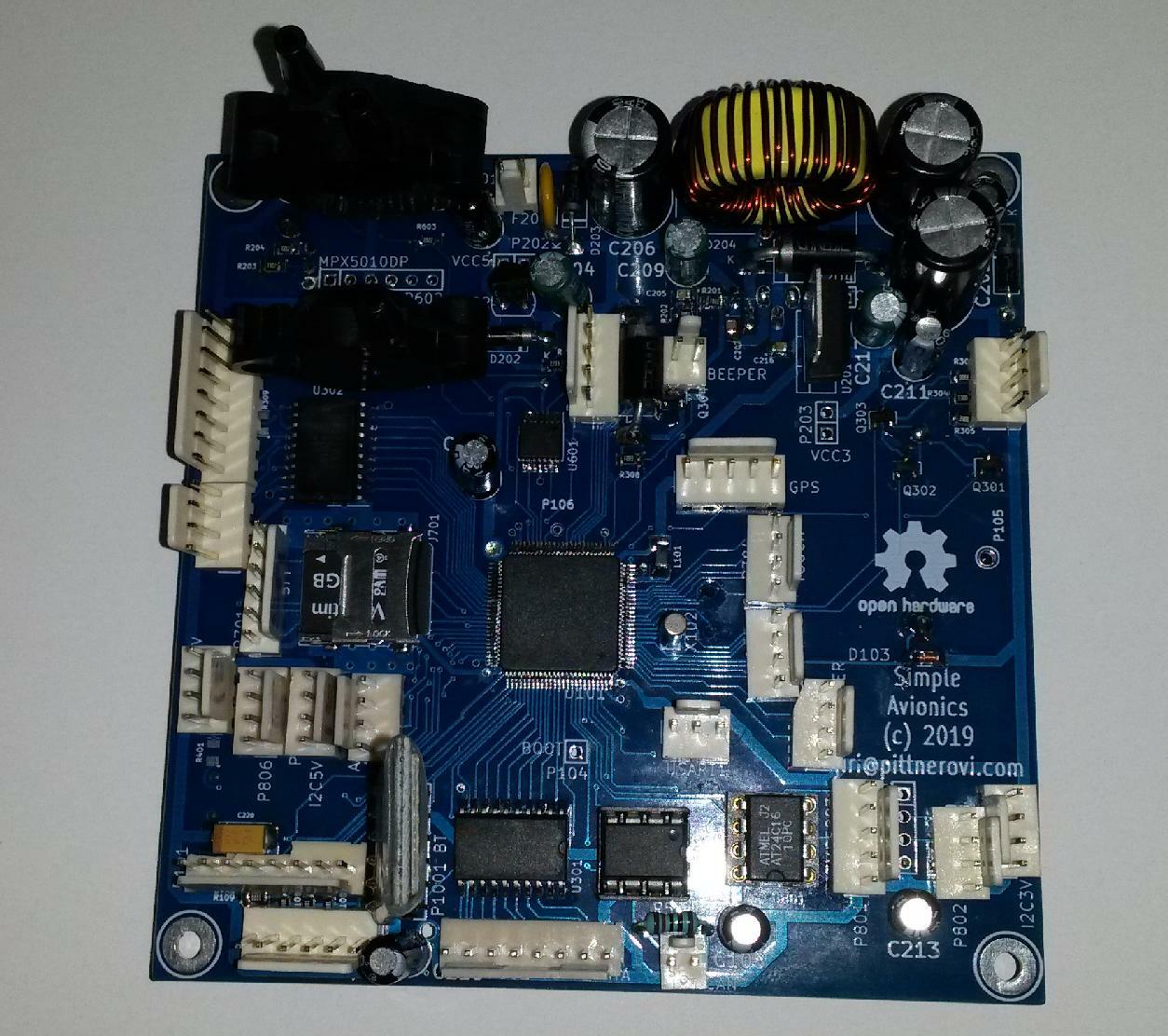
At the moment the project is the experimental phase. I have drawn schematics in Kicad, for easy inspection here is a PDF version. The schematics/board is rather experimental, merely with connectors for the various modules, since it is not sure, which will work best and will be used in a final version. I have also designed a PCB, 100x100mm 2-side FR4 board without any extras to make the fabrication inexpensive at Seeedstudio. The complete Kicad5 design files are available in a zip file. The final PCB board is shown below:Front side of the assembled PCB
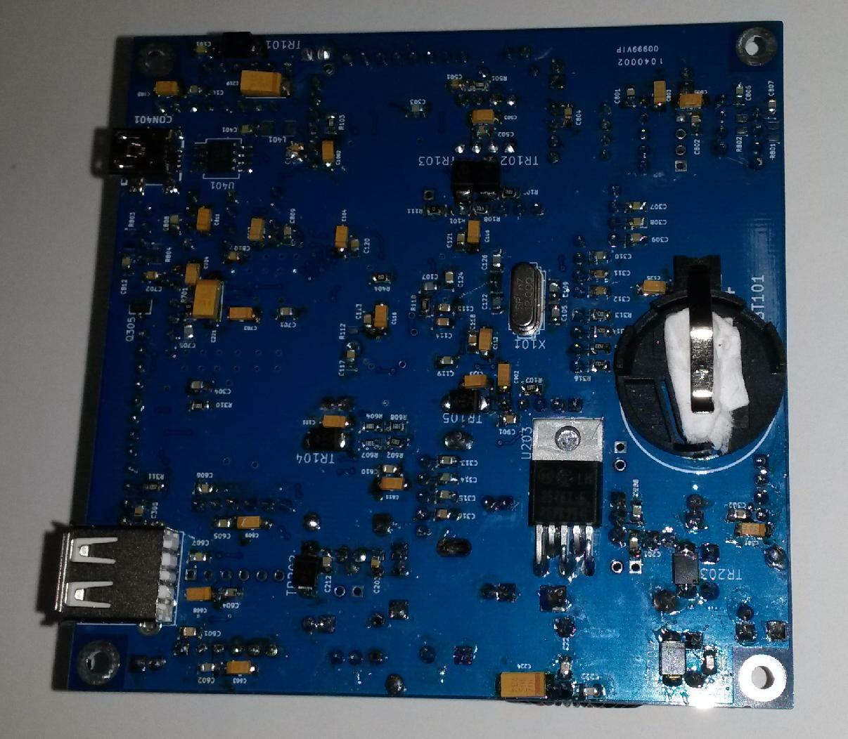
Back side of the assembled PCB
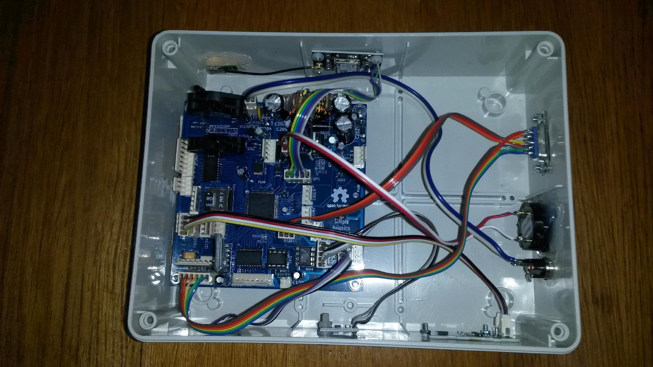
Bottom part of the assebled device
Top part of the assebled device
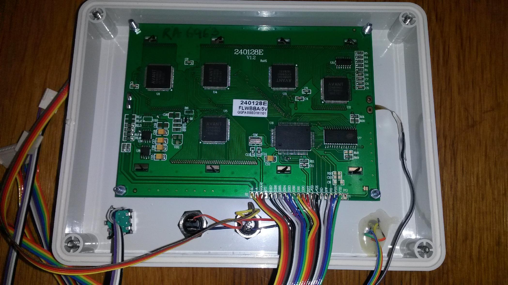
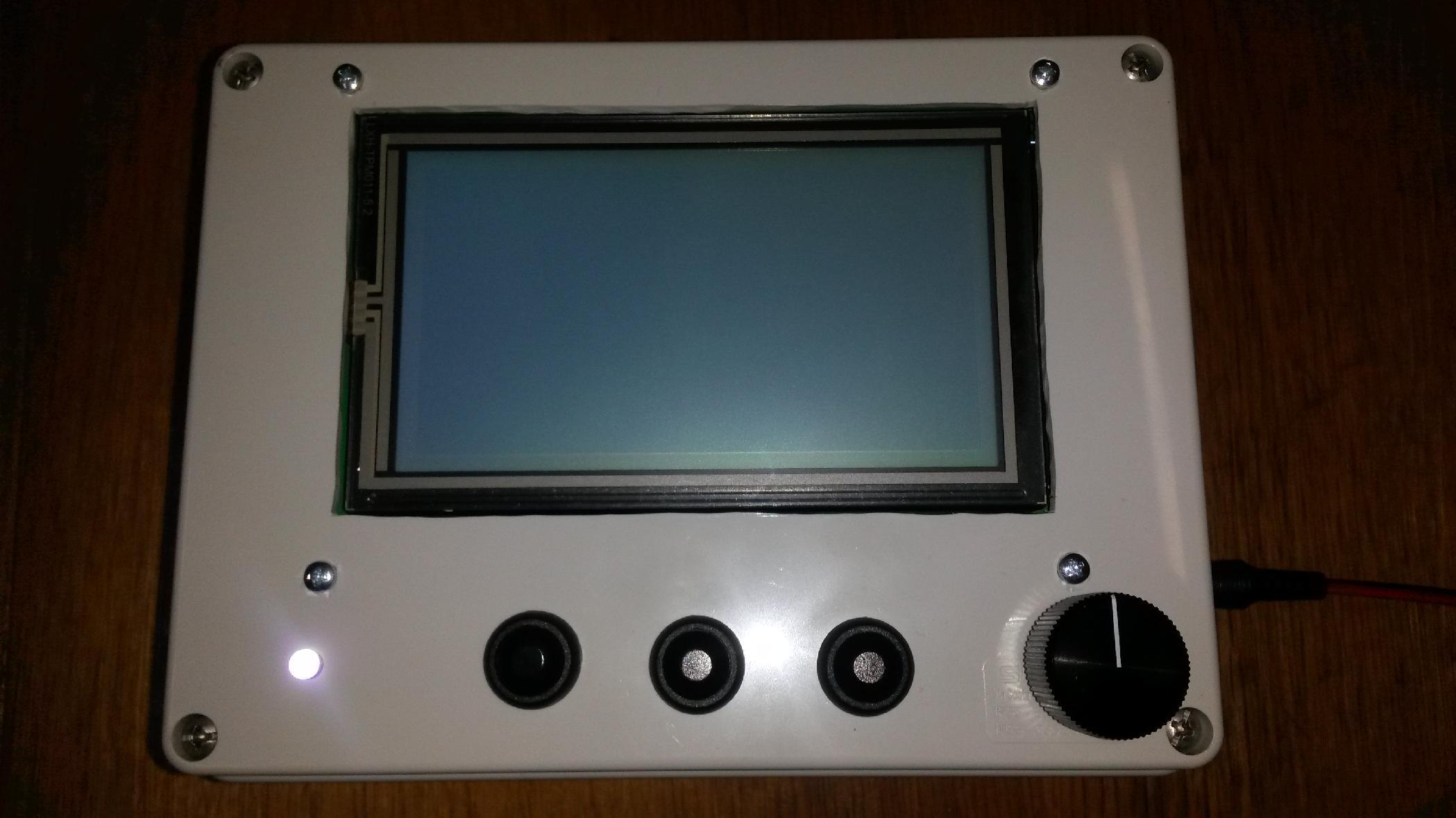
Front panel of the assebled device
Warning about crap HMC5883 modules from Aliexpress
Unfortunately during the development I have lost considerable time debugging the I2C communication with HMC5883, while the culprit was not my hardware or code, but a malfunctioning HMC5883 module from Aliexpress (the blue one on the picture below). Then I obtained another HMC5883 module from Olimex.com (the red one on the picture below), which worked right just at the first power-on. Later I found that the bad module might contain a QMC5883 chip rather than the claimed HMC5883, cf. here and here.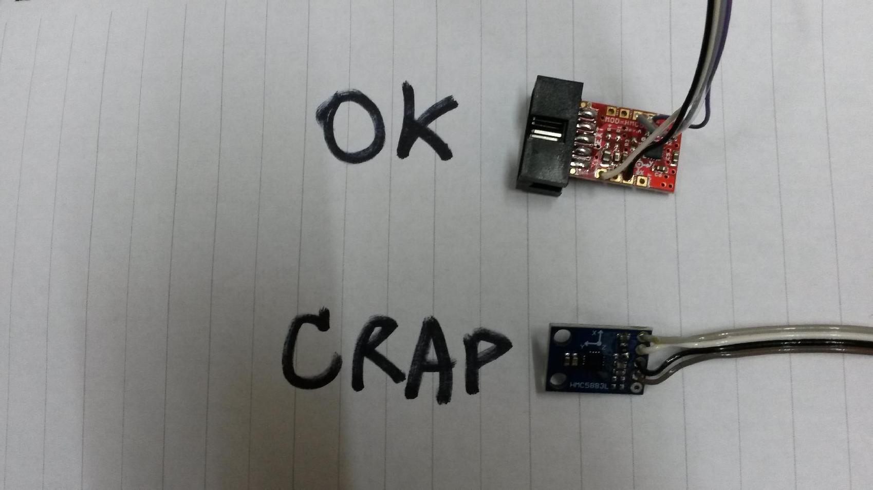
Open source firmware design for the DIY experimental avionics
Presently the code is in a very early stage, see avionics.cpp in the tar.gz file stm32f37.tar.gz.However, two points became clear:
1. To function properly in a plane, the measured accelerations have to be corrected for non-inertial forces to yield pure (rotated) gravity vector, which is in turn used as reference in the AHRS update (fusion) algorithm. So any fusion algoritm which does not include GPS input cannot work properly in flight. Consequently, any "artificial horizon" smartphone application which relies on a fusion algorithm inside the accelerometer/gyro/magnetometer chip or a system library which does not employ GPS input must fail.
2. An improved AHRS algorithm has been published recently, which should be much better than original Madgwick's one.
Taking these two points into account it should be straightforward to make a robust AHRS IMU implementation. First tests confirm that the new algorithm works better, faster settles after rotating the device. GPS processing and code optimization will follow, as well as code for pressure instruments, graphical output etc. etc.
I have implemented the new AHRS fusion algorithm in C++, developing a quaternion library, to express the algorithms more elegantly, directly in terms of quaternion and vector algebra. Indeed, the whole algorithm employing the Quaternion class methods takes whole 30 lines of code including comments!
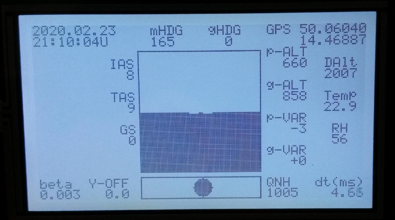
Positive is also that the AHRS algorithm works fast, even when I did not employ any optimizations based on sparsity of the reference vectors yet, the calculation of BOTH Magdwick and new algorithm and printout to the display takes just 7ms on the STM32F373@72MHz, as you can see in the right upper corner where dt is printed (10ms is an extra added sleep time). Actually, most time takes the printing to the display, the AHRS update is just 0.3ms thereof and there is not much difference between the general version and the one optimized for sparse reference vectors.
Open source implementation of the new AHRS orientation algorithm for IMU sensor fusion
I have put together a short text on the math involved in the AHRS algorithm , in a PDF form which is more suitable for typesetting formulas.The open source GPL licensed sensor fusion algorithm, which combines accelerometer, gyroscope, magnotometer and GPS data to compute orientation with respect to Earth frame of reference is in the file ahrs2.cpp in this archive stm32f37.tar.gz. See also quaternion.h, quaternion.cpp, vecmat3.h and vecmat3.cpp for implementaiton of quaternion algebra and SO(3) rotations. The fusion algorithm has been described in the papers:
"Improved Formulation of the IMU and MARG Orientation Gradient Descent Algorithm for Motion Tracking in Human-Machine Interfaces" by Marcel Admiraal, Samuel Wilson, Ravi Vaidyanathan, in 2017 IEEE International Conference on Multisensor Fusion and Integration for Intelligent Systems (MFI 2017)
and "Formulation of a new gradient descent MARG orientation algorithm: Case study on robot teleoperation" by Samuel Wilson, Henry Eberle, Yoshikatsu Hayashi, Sebastian O.H. Madgwick, Alison McGregor, Xingjian Jing, Ravi Vaidyanathan in Mechanical Systems and Signal Processing 130, 183-200 (2019).
The treatment of non-inertial forces for in-flight operation has been implemented based on the description in the standard textbook on avionics: R.P.G. Collinson, "Introduction to Avionics Systems", 3rd edition, Springer, Dordrecht Heidelberg London New York 2011 ISBN 978-94-007-0707-8 DOI 10.1007/978-94-007-0708-5.
Presently a preliminary version of the firmware has been written which supports the most important functionality: MEMS and magnetometer sensors, differential pitot and static pressure and computation of related quantities, quaternion computations for the AHRS algorithm, temperature and humidity sensors, graphical touchscreen, GUI, GPS support, SDHC card support with USB mass storage, FAT filesystem and datalog, USB serial virtual com port support are all done. However, it will require a lot of testing. Presently it runs well on an a desktop, but has some issues related to vibrations and magnetometer interference when tested during a drive in a car, which will require some effort to resolve. Only after a successfull operation in car is achieved, in-flight tests will follow.
During 2020 and 2021, I have implemented a calibration of the magnetometer, which turned out to be absolutely essential to yield correct magnetic headings, and I also developed a simple implementation of the World magnetic model, which can be used to compute magnetic declination at any point at the Earth and convert thus between GPS and magnetic headings. Further it became apparent, that a-priori calibration of the magnetometer is not practical and I have developed a continuous re-calibration approach, which accumulates data for least-squares fit and periodically updates the fit data and lowers the weight of old data. I have also adopted full 3D calibration approach, as described in the ST Design Tip DT0059 by Andrea Vitaly in 2018. For simplicity and numerical stability, I have chosen the non-rotated ellipsoid fitting approach, which seems to yield adequate results.
I have also noticed that in recent years (2020-2021) several companies developed commercial EFIS systems for small aircrafts, which have affordable pricing (e.g. AvMap Ultra, Kanardia Horis, Flybox OBLO, LX Iris EFIS etc.). Obviously I was not alone who had the idea to use the modern MEMS sensors to build such a device :-). However, I don't mind it, I never had the ambition to develop a commercial device, I rather worked on this project for my own education and enjoyment as a hobby, so I plan to continue and bring it to a working prototype stage.
News 2022: I performed a first in-flight test of the device, recording a debug flight log. The flight included several traffic patterns, a cruise flight with climbs and descents, and a few 360-degree turns in about 30 degrees bank in both directions. Unfortunately, I could not connect the device to a pitot/static ports in a rental plane ;-), so these features could not be tested. Altimeter used just the ambient cabin pressure.
Further development of the software for my device will take definitely some time, since a lot of testing under realistic conditionsi will have to be done. As a pure hobby project it has a relatively low priority on my TODO list, but something new should appear here in the future...
My Electronics page
My hobby page
My main page with e-mail contact
TOP of my family pages