Starting with LPC1343 ARM Cortex-M3 chip
If you need a more powerful Cortex-M3 core, higher frequency (up to 72MHz), 8K RAM, or hardware USB support with a minimal modification to previous design based on LPC1114, the LPC1343 chip is a good choice. It is almost fully pin-compatible (except pins due to the USB) and has almost identical peripherals (except SPI1). Moreover, the memory layout and memory mapping of the peripheral registers is identical.Note that in LPC1343 the bootloader can work also via USB, so for backward compatibility of the programming it is necessary to pulldown PIO0_3 during RESET. To use the USB mass storage bootloader, simply from command line
dd if=new-firmware.bin of=/dev/sdx seek=4
See more details here.
Due to the similarity of this chip to LPC1114 I share the development directory for them and switch between them by commenting/uncommenting a few lines in Makefile. Tar archive of the whole directory with several open source projecs is arm_lpc111x.tar.gz.
USB virtual serial port (/dev/ttyACMx) communication with LPC1343
In 2018, I have designed a board with LPC1343, USB connectivity and ENC28J60 module and a few other peripherals, intended for further development, see PDF schematics and a complete Kicad design. The USB connectivity makes it possibly to avoid UART in the command line communication with the firmware and rather direct it via USB (without a need for FTDI or similar convertor). In the file ttyacm.c from the arm_lpc111x.tar.gz archive is a skeleton program which reads commands from both UART and USB (/dev/ttyACMx under linux), and responds with output to appropriate destination. I have further used this approach in a module with LPC1343 and RFM22B transceiverUPDATE 2017:
The LPC1114FN28 in DIP package is now obsolete, hard to obtain and expensive. Since I had a few boards still designed for it (itead makes 10 pcs minimum) I have designed a PCB adapter from LPC1114FBD48/302 in LQFP48 package to DIP28, which provides a pin-by-pin compatible drop-in replacement of LPC1114FN28. Fortunately, LPC1114FBD48 makes available all pins with the same function combinations as in LPC1114FN28, just exports a few more from PIO2 and PIO3, so this is possible. Here is the Kicad design of the adapter, including Gerber files for production. Another advantage of the LPC1114FBD48 chip is larger RAM (8K rather than 4K). For new designs, for example the LPC board with ethernet interface I use thus this package.Starting with the LPC1114FN28 ARM Cortex-M0 chip in DIP package: crosscompilation and flashing mini-howto (from a linux command line)
If you need more speed than 8-bit MCUs like Atmel AVR can deliver, yet a device running Linux operating system like Raspberry Pi would be an overkill, and you do not want to use demo-boards like the STM32F4 Discovery kit, but to solder everything from scratch, you can conveniently try the LPC111x series, in particular LPC1114 chip which ins the version named LPC1114FN28 provides an ARM Cortex-M0 core and a few peripherals in a DIP28 package at a cost lower than ATmega8. For simple applications this low-end ARM is sufficient and as I will show below, development for it is not more difficult than for 8-bit MCUs.
The same GCC toolchain from launchpad.net, as I used for STM32F4 Discovery kit can be used to cross-compile for this device.
Moreover, you do not need any JTAG adaptor to program it, just a USB-serial convertor module based on FT232 or FT2232 etc. will do, since the LPC chip has a built in serial bootloader. LPC1114 is 5V tolerant on its GPIO pins (except when they are configured as ADC inputs!), so the same tool used with say ATmega MCUs can be employed here. (Do not use a cable yielding RS232 voltage levels directly of course, use MAX232 to convert it.).
Download the lpc21isp code from Sourceforge, add a line "{ 0x1A40902B, "1114FN.../102", 32, 4, 8, 1024, SectorTable_17xx, CHIP_VARIANT_LPC11XX }" in the array of supported devices in lpcprog.c, and compile it. UPDATE: Version 1.85 of lpc21isp already supports the chip and no source modification is needed.
To load and start the program, connect PIO0_1 to GND (e.g. jumper), reset the device (PIO0_0 to GND pulse), the run the lpc21isp program (see below), remove PIO0_1 jumper and reset again. I used the following command line to flash the MCU:
lpc21isp -NXPARM firmware.hex /dev/ttyUSB0 115200 14746
The last number is your crystal frequency in khz, but it seems irrelevant anyway (worked with a different number too).
Programming LPC111x by lpc21isp from Raspberry Pi
I have considered to build a device combining Raspberry Pi with some additional circuitry for real-time tasks based on LPC1114, whre Raspberry Pi shound besides remote access make remote firmware updates in the LPC processor possible. I tried the above procedure, connecting PIO0_1 and PIO0_0 to 2 gpio lines of RPi and connecting the serial ports - but it did not work. Using an oscilloscope, I have found the reason - due to some kernel driver bug, RPi's /dev/ttyAMA0 serial port generates a spurious pulse on the TX pin at the time of open() system call, even if opened for reading! This pulse then confuses the bootloader of LPC1114 so that synchronization attempts by lpc21isp fail. Rather than attempting to fix the ttyAMA driver, I have found a wayaroung - starting a trivial program which open()s /dev/ttyAMA0 for read and waits a few seconds before closing it, just before toggling the RESET and BOOT gpios and calling lpc21isp. In this way the spurious pulse happens before resetting the LPC processor, luckily second open() called from lpc21isp does not generate the pulse when other process is holding a descriptor to already opened ttyAMA0 device.The same bug may affect also attempts to program any other MCU over a serial bootloader from RPi, of course.
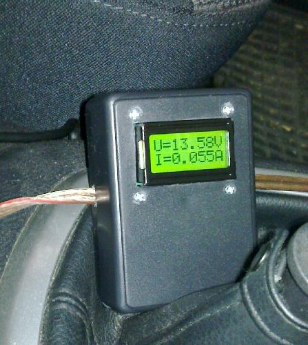
Simple project with LPC1114FN28: volt/ampere meter for a car battery charger
As a little project to have a try with this MCU I decided to build a simple Volt/Ampere meter to check the trickle-charging of a car battery from a 13.6V power supply. The hardware is essentially trivial - 7805 and LE33 with capacitors to provide power, 14.7456MHz crystall with 2x 18pF capacitors, voltage divider to sense battery voltage, 0R1 shunt to sense current with a 4x non-inverting amplifier based on 1/2 LM258 powered by 3V3 to prevent ADC overvoltage, connected to ADC1 and ADC2. Display 2x8 characters with a HD44780 controller is connected to GPIO0_2-9 (see lcd.c for details). I have built it on a pre-drilled prototyping board, handwritten schematics is here. You can see the result at at this picture.
Concerning software, I started from the excellent code-base by microbuilder.eu. Printf and scanf from the usual stdio will overflow the flash size of LPC1114, so I added %f to the mini-printf provided by the microbuilder.eu code-base. I have also added lcd.c supporting HD44780 controlled LCD text displays. I have provided sbrk() and modified the linker script to provide malloc()able heap and customized the Makefile. I have modified the PLL initialization to facilitate different frequencies of external crystal and put it outside of main(). I have made other modifications to uart, adc and a few files and stripped out the code not needed for this project. (Notice that the microbuilder.eu code-base is a bit specific for some demo board, for example it was allowing ADC1-4 by default, which might interfere with other uses of the pins, so you should not use their code blindly.) The resulting source codes are here.
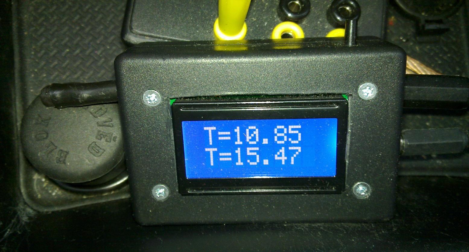
Another simple project with LPC1114FN28: thermometer with two SMT160-30 sensors
I have built an indoor/outdoor thermometer for use in a car, since the thermistor of a cheap chinese product did not survive the outdoor winter conditions and gave up after 2 months. I decided to dedicate another LPC1114 from the batch I recently purchased for this purpose and to employ the SMT160 temperature sensors in TO92 package, protecting the outdoor one with a lot of silicone and heatshrink tubing... The indoor one must not be built in the device itself as it would be biased by the heat generated by display backlight and 7805 regulator. The sensors yield a pulse-width modulated signal, which is conveniently measured by the input capture of a 32-bit counters and results of measurements are summed by an interrupt handler and averaged over many measurements - cf. lib/smt160.c. A relative precision of 0.01 Celsius degree is easily achieved, although the absolute accuracy is of course much worse. The sensors must be connected to PIO1_0 and PIO1_5; the external one is connected via a shielded pair line, with additional protection by clamping to GND and VDD via a pair of BAT42 and 1nF bypass capacitor, to minimize possible EMI effects. Power to the device is protected by a transil connected before the 7805 stabilizer. Alphanumeric display is connected as described in lib/lcd.c. The MCU is clocked by 14.7456MHz crystal with PLL=3 (which can be changed of course, I had just a spare crystal of this value). The resulting source code is thermometer.c in the tar archive here, which contains also Makefile and the library files.
To conclude, I think that 8-bit MCUs from Atmel and Microchip have got a strong competitor, which is simple to use also in hobby applications. However, there are some things remaining on a wish-list, which are available for example in some ATmegas: EEPROM on chip, DIP-40 version with more GPIOs, second UART, differential ADC channels with programmable gain (i.e. op-amp on chip), accurate voltage reference for ADC on chip, larger flash/ram versions in DIP packages to accommodate full-blown soft-floating point. Perhaps STM should put some of their STM32F37x chips in a DIP40 package :-).
Update 2020:
As I planned to build another device like this, I finally designed a PCB encompassing both the thermometer and VA meter. It is fully open hardware, schematics is vatmeter.pdf and Kicad design files are in vatmeter.zip. For thermometer, no code change in thermometer.c is needed, for VA meter you just need to change ADC pins in the code vameter.c to match the schematics. The sources are in the tar archive arm_lpc111x.tar.gz,
Another project based on this microcontroller is the Wireless electromotoric code lock based on LPC1114
Another project based on this microcontroller is the thermostat which uses a stepper motor to turn a valve open/close
Another project based on this microcontroller is the Frequency changer based on LPC1114
My Electronics page
My hobby page
My main page with e-mail contact
TOP of my family pages