Frequency changer - variable frequency three phase true sine wave AC/DC/AC convertor with the LPC1114FN28 ARM Cortex-M0 chip
For one application I recently needed to control the speed of a 1-phase asynchronous motor. Unlike commutator motors, which can be easily regulated with a triac, asynchronous motors require a frequency changer (convertor), also called variable frequency motor drive (VFMD), for this purpose. Although such devices are in recent years readily available on the market in many power categories, thanks to the progress in MOSFET and IGBT transistor technology, they are still targeted more towards industrial customers, with corresponding pricing. So I thought I could build one specified for 230V 50Hz 1500VA -> 230V 10-100Hz 1500VA myself for lower price. However, on aliexpress you can now find quite cheap frequency changers, which are probably satisfactory for a hobby use. I tried my own construction anyway, just for the fun of learning more about power electronics.I was also considering to use such a device to generate true sine wave AC from either DC or "modified sine wave" AC, since true sine wave DC/AC converters are much more expensive than "modified sine wave" DC/AC converters of the same power rating. (High voltage DC can be obtained from any high-power DC/AC convertor, bypassing its second stage.) The VFDs do not filter the outgoing PWM signal, omitting the power inductors and capacitors for cost effectiveness. However, I tried to use "modified sine wave" DC/AC convertor, feeding its output to a frequency changer, and passing its output through a LC filter (same as below). This generated an acceptably good sine wave, however, with some spikes caused probably by not accurate timing of the sine-modulated PWM carrier - at least for the "Rilipu" cheap Chinese frequency changer. So this is an option how to possibly make cheaper "true sine wave" DC/AC convertor, if you don't mind that it consists of 3 boxes cabled together. My device described below is, however, able to generate much cleaner sine wave that the cheap Chinese frequency changer, though.
The simplest category of frequency changers follows the scheme AC -> DC -> AC, first rectifying the mains voltage and then generating true sine wave by PWM technique, where the pulse length is modulated to form a sine wave after low pass filtering and the target sine wave frequency is synthesized using the direct digital synthesis (DDS) method. The second step of this scheme is shared with the DC/AC converters, which convert e.g. 12V from car or solar system to 230V/50Hz, which have two stages, the first generating 400V DC with a high frequency isolated DC/DC convertor and then doing the same DC -> AC sine wave synthesis step, however, with a fixed frequency.
There are several datasheets and schematics available, the core of the DC -> AC changer is a full H-bridge (or 3 half-bridges for 3-phase application) with MOSFETS or IGBT transistors, an appropriate gate driver, and controlling MCU. For schematics of an interesting IGBT bridge see here. Interesting application notes on this topic have been quite recently written by the manufacturers of relevant components, for example frequency_convertor_motor_drive_design_AN1660.pdf, and dc-ac-800VA-inverter-TI-appnote_with_waveforms.pdf and dc-ac-2stage-1kw-invertor_AN2794.pdf. I have decided to use the IRS2184 half-bridge drivers, which take care of dead time to prevent cross-conduction of te bridge and require just one polarity signal and one shutdown signal. More on the hardware design will follow below.
I have developed a rudimental Spice simulation of the operating principle of the device (2 phases 180 degs. shifted), which can be found in the file simul1pwmsine.tar.gz.
Second point to decide was which microcontroller to use for this purpose. I wanted to make this choice and program and test the DDS PWM sine wave synthesis before going further and designing schematics or even building the device, just as proof of concept of the feasibility. I have seen on the internet some Arduino Atmel AVR code for this purpose, but I did not like it much. The reason was that it had to use fixed PWM frequency given by the TOP=256 of the 8-bit timer counters available in the 8-bit MCU.
So my consideration went to 32-bit ARM Cortex MCUs, which I have been working with since couple of years ago. I have discarded the idea of using my favorite STM32F37 series, as being too costly and overkill for this purpose. So the natural candidate for this task remained the NXP LPC1114FN28 chip, which is cheap, in a hobby-friendly DIP package (no miniaturization possible due to the power components anyway), I have used it in several projects before, and conveniently I still have a few of them in in my hobby lab, since I had to purchase a batch of 12 pieces...
True sine wave generation using LPC1114FN28 (ARM Cortex-M0 32-bit MCU) with software based direct digital synthesis (DDS) and PWM modulation (GPL open source code)
LPC1114FN28 has two 32-bit counters, each with 4 independent match registers MR0-3. I decided to use CT32B1 and its MR0-2 for PWM generation of 3 phases, while MR3 servers as TOP for the counter, defining the PWM frequency. DDS synthesis of the sine is performed via an interrupt routine, which after each TOP match updates the values in the PWM match registers from a precomputed table of the sine function. The 32-bit ARM MCU has the advantage of fast 32-bit arithmetics, so the interrupt routine can, besides accumulating 32-bit DDS phase increments, also scale the values of the sine samples to match the current TOP value for the particular PWM frequency of choice and also it can scale down the PWM width to generate a target effective voltage. Moreover, in the initialization routine floating point calculation can be done in the MCU, which has large enough flash to hold the code. So I think the low-end ARM chip is much much better suited for this purpose than the poor 8-bit MCU and thanks to its capabilities, my code can arbitrarily vary the PWM frequency, the target DDS frequency, as well as the target effective voltage, which can be employed to implement the simple "V/f" scalar motor control.For introduction to the programming for LPC111x chips, see here.
The code ddsgenerate.c to be compiled and executed on a PC generates the sample table of sine function, with selected sample rate and resolution. I have used 10 bit sample rate (1024 samples) each of uint16_t size, see the generated header file sin_10_16.h. The source code of the MCU's firmware is pwmsine.c. It is closed to finished working version. The most interesting point was how to cope with the finite duration of the interrupt routine doing the DDS, which of course interferes with the PWM generation. Look in the code for the hack how I solved it :-).
The whole tar archive which includes supporting libraries, headers, Makefile and linker script (and sources of my other project with this MCU) is arm_lpc111x.tar.gz.
Open hardware schematics and design and gerber files for a frequency changer with the LPC1114FN28 ARM Cortex-M0 chip
I have decided not to implement any vector control based on voltage-current magnitude and phase measurement, this would require too much development effort for a hobby project (and a MCU with more ADCs and IO lines). However, in contrast to just variable frequency drives which do not filter high frequecy PWM component, I have decided to implement filtering, so that the output of the device should be pure sine waves without harmonics, similarly to true sine wave DC/AC convertors. It makes the device more expensive due to the large LC components, but also more universally usable - it can be used to upgrade a cheap "modified sine wave" single-phase DC/AC convertor to a three-phase "true sine wave" DC/AC convertor.Another simplification of this design is the lack of any power factor correction circuitry.
I have designed a schematics pwmsine.pdf (this is updated, final version) and a board using Kicad, the design and Gerber files are pwmsine.zip (layout of the respin not finished, cf. below). The board is quite large and to carry the large currents, 2oz copper is used and solder mask is partly removed, to strengthen the critical parts by adding extra thick layer of additional solder. I have considered a 2-board design, but that is presently a bit cumbersome in Kicad. I have found a Chinese PCB fabrication service leappcb.com, which was willing to produce just 2 boards for much better price than Iteadstudio produces 5 (unneeded) pieces, and it accepts safe Aliexpress payment.
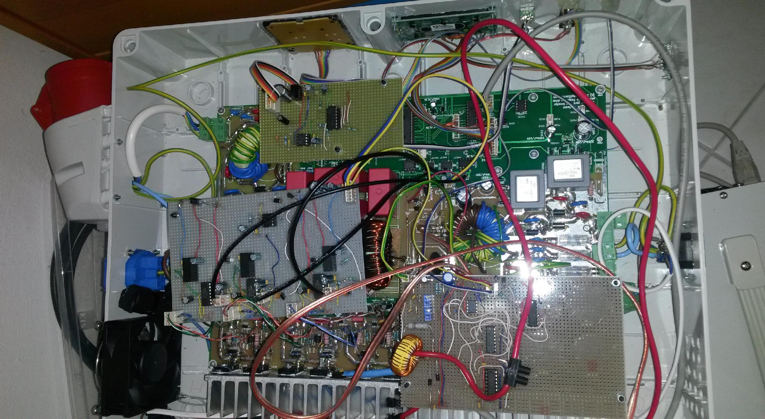
As you can see on the photo of the mess, my original design had several flaws and fixing them required addinional circuitry or substantial changes :-). I mainly had to add fast in-hardware short circuit and overcurrent protection to achieve reasonable robustness and avoid transistor damage during software degugging. Also, I changed the drivers, now using the IRS21844 with split logical and power grounds. Finally, I use output voltage RMS measurement by a hardware chip, original idea to sample the sine wave and do RMS in software (ADC interrupt based) caused irregularities in the DDS generation, as the ADC interrupts competed with PWM timer interrupts and the MCU was too slow to service both.
I finally decided not to respin the board, since adding the extra circuitry would make it impractically big. So the Kicad files pwmsine.zip contain up-to-date schematics and component list, but on the PCB I have just placed the footprints and did not finish the respin of wiring, since I have no intention to get the board respin actually manufactured. For a new work inspired by this page, I would strongly recommend to split the device to several smaller boards, perhaps (1) input filtering and rectification, (2) power MOSFETS, drivers, overcurrent protection (3) output filtering and measurement, (4) isolated logic and control.
If I would start from scratch again, I would also dedicate one MCU just to user interface, measurement and control, and use another MCU or CPLD just for the DDS PWM sine wave generation. The capabilities of LPC1114 at 44MHz are almost exhausted, in order to do smooth motor start I do a lot of floating point calculations in the interrupt routine and use a kind of 'double buffering' of the PWM registers, since the interrupt takes much too long, the CPU spends more time in interrupts than in main code!.
In the end, it was an excellent exercise for learning power electronics, but both the developemnt time and cost for instruments I have purchased (differential high voltage scope probe, current scope probe (iProber), high voltage laboratory power supply, 2kVA safety isolation transformer), not to speak about the cost of a few burnt IGBTs and drivers, far exceeded my original expectations. Definitely it was not a 'right on the first time' project, and mistakes in power electronics design are much more damaging than in low voltage circuitry, software bug manifesting itself in rare glitches can cause expensive power transistors to explode ;-). So if you want to get experience with design, you are right here, but if you need a cheap VFD or need it quickly, go to Aliexpress, one cannot beat their prices anyway!
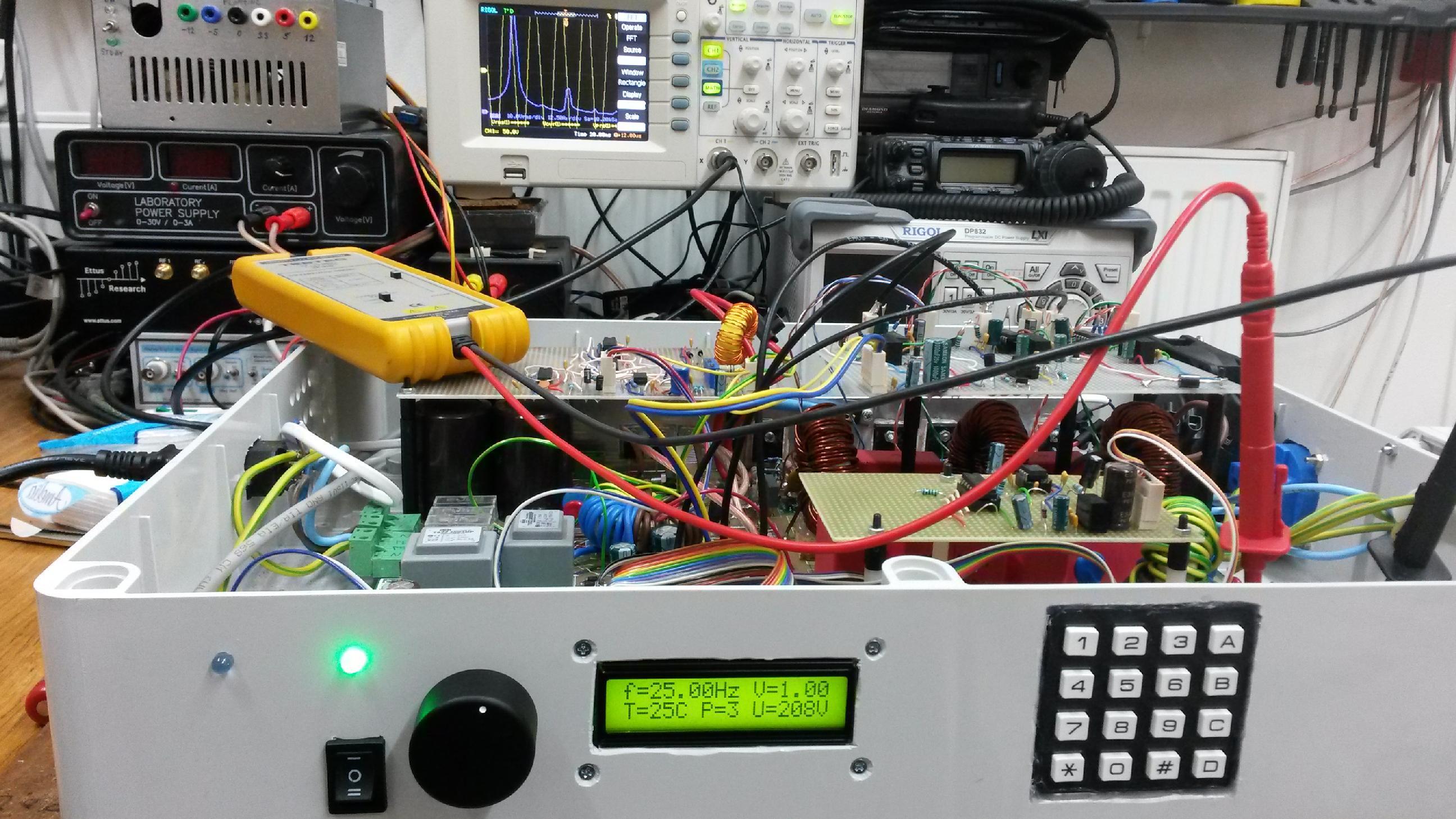
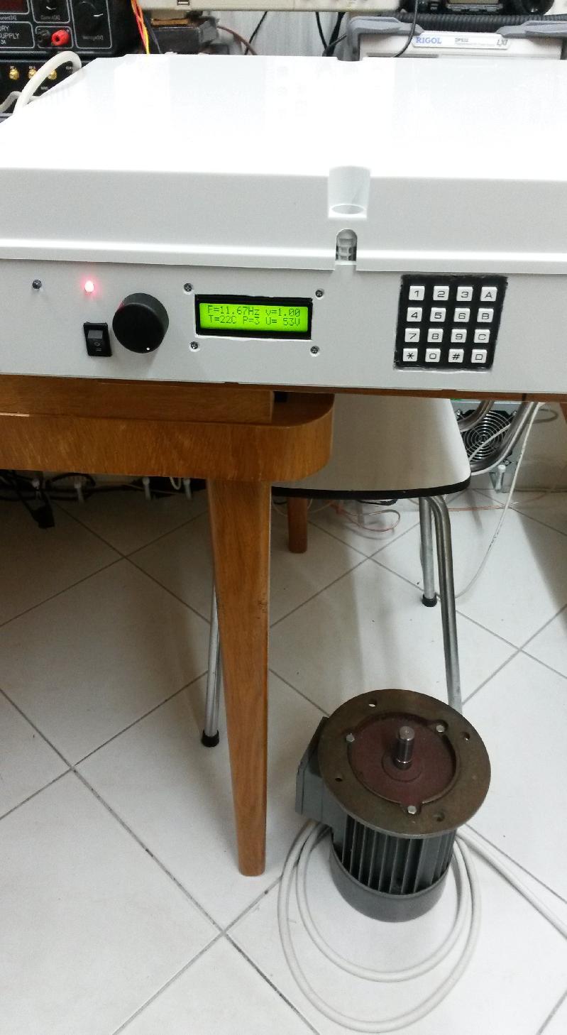
Now a few pictures of running the prototype:
Scope screenshot running at 25Hz single phase mode, loaded by 60W light bulb
Scope screenshot running at 75Hz single phase mode, loaded by 60W light bulb
Scope screenshot running at 50Hz single phase mode, loaded by 60W light bulb, using the `enhanced' sine waveform - notice the higher Vrms
Scope screenshot running at 100Hz three phase mode, unloaded
Scope screenshot running at 15Hz three phase mode, loaded by a 750W asynchronous motor without a mechanical load
Notice the lower Vrms due to V/f control
Working as a VFD for a 3-phase induction motor:
Obviously, the sine wave is not perfect, even in unloaded case, mainly due to the restriction of PWM due to interrupt duration. When loaded, other effects come into play. It is certainly good enough for a VFD, but not really a good variable frequency laboratory AC power supply.
I have also noticed a significant voltage drop when the output is loaded by a large resistive load (2kW heater). THe problem was already in the input rail - perhaps bigger-size rectification diodes and larger filter capacitors would help. Some losses can also be attributed to the output filter and switching transistors. For application as a variable frequency 3-phased motor drive, the output filter can be omitted, improving the efficiency. In order to completely eliminate voltage drop on heavy loads, one would have to work from higher rails (using voltage doubler rectifier) and implement control loop from output voltage to the PWM 'volume' parameter. However, the higher rail voltage would exceed the IRS21844 capabilities (from 230V mains) and therefore I did not implement it. IGBTs for higher voltages are readily available, but I did not find IRS21844 functional alternative capable of higher voltage.
Concerning the choice of IGBT transistors, I would possibly recommend the HGTG10N120BND type rather than of IRG4PC50W. HGTG10N120BND contains internal diode and should be more robust with respect to microsecond long short circuits, as it is the NPT type IGBT.
The measured DC bias of the AC wafeforms was below 3V at 1-phase 240V AC, and below 0.3V for 3-phase 220V AC at maximum amplitude.
Some references on power electronics
Some quick information on the web:
A link to a simple howto for a SMPS transformer turn number calculation is here.
How to make a Spice model of nonlinear saturable core: here
Excellent in-depth books which cover magnetic components and switching convertors are:
Robert W. Erickson and Dragan Maksimovic - Fundamentals of power electronics, Kluwer, 2004 (second edition)
Abraham I. Pressman, Keith Billings, Taylor Morey - Switching power supply design, McGrawHill, 2009 (third edition)
Steven M. Sandler - Spice circuit handbook, and other books on SMPS modelling by this author
Christophe P. Basso - Switch-Mode Power Supply SPICE Cookbook
Timothy L. Skvarenina (Ed.) - The power electronics handbok
George C. Chryssis High Frequency Switching Power Supplies Theory And Design
Marty Brown Power Supply Cookbook - Second Edition
Colonel Wm. T. McLyman - Transformer and inductor design handbook Third edition
Another project based on this microcontroller is the Wireless electromotoric code lock based on LPC1114
My Electronics page
My hobby page
My main page with e-mail contact
TOP of my family pages