Wireless electronic code lock based on LPC1114FN28 ARM Cortex-M0 microcontroller with a homebrew electromotoric locking cylinder and a high security lock (Open hardware and open source DIY hobby construction)
Update 2021: A new respin of the board was developed, to suport more modern RFM22B transceiver module: zamek_v2.pdf and zamek_v2.zip. Similarly, the new keyboard board is keyboard433_v2.pdf and keyboard433_v2.zip. the corresponding firmware will be published when available.
Electronic door lock has been another project of my hobby effort, with the aim to either increase security, which is rather miserable with overwhelming majority of locking cylinders or to allow access by password, or remote opening via internet (for example in the case of emergency access when not present). The commercially available electronic locks are usually very expensive (both electro-motoric cylinders like EVVA EMZY, KESO MOZY eco, and EMZ or electromotoric locks which require special door installation like e.g. Abloy), often the mechanical parts are sold inseparably with an electronic control unit which offers no security at all (ATR-only RFID or Mifare classic) or miserable one (Mifare Desfire was hacked too), and moreover they are all proprietary and thus cannot be really trusted (backdoors designed on the request of NSA ;-))). For detailed information about access control security see a SRLABS document on access control best practices. I have thus designed my own solution spanning the whole system - from the mechanical components over electronic hardware up to software. Since I have no time to develop and sell such products commercially, I am publishing it here as open hardware/software for the benefit of anybody skilled enough to implement it himself. If you decide to build your own one and succeed, drop me an email ;-). Bug reports and hardware/software patches/improvements/suggestions are also appreciated. However, I cannot provide support beyond fixing my own bugs/design flaws (if you point them out). Particularly I do not teach hardware/software development for microcontrollers to beginners via e-mail, sorry. I gladly admit that the EVVA eletromotoric cylinder has much nicer design than my home made one ;-), but the cost of the diy one is much lower and the above described advantages in security and flexibility apply.
Design goals / features of the lock:
1) Closing/Opening from outside (untrusted area) by an 8-digit password on a keyboard, which has no galvanic connection to the lock.
2) Closing/Opening from the inside (trusted area) by a button touch, indication of the state (locked/unlocked) by a LED
3) Remote Closing/Opening from the internet - indirectly via an embedded linux server, which will send wirelessly commands to the lock
4) Fixed passwords stored in flash and variable passwords stored in EEPROM are supported. The fixed ones can be changed only by firmware reflash; the variable ones can be programmed via UART command line interface (accessible from the trusted area) or wirelessly from the embedded linux server (the wireless transfer being encrypted of course).
5) Variable configuration - either adding comfort and remote control to an existing mechanical lock, with a possibility to still open it mechanically in case of failure - but no security enhancement, or setup when BOTH mechanical and electronic lock have to be opened, with no mechanical backup - increasing the security of the overall locking system to a reasonably high level. For the latter, reliability of the operation is critical, indeed. Both versions (requiring a different mechanical setup, but sharing all the electronic hardware and most of the software) have been installed and are shown on photos below.
6) Reliability: The lock has been in reliable operation since 2005 (AVR ATmega based version, mechanical setup increasing security, unpublished) and since 2013 (ARM LPC1114 version, mechanical setup without security enhancement, published here) and no problems have been encountered.
7) A PIR sensor and/or door magnet sensor can also be connected to the lock's electronics, which will forward wirelessly its signals when the lock is in 'locked/armed' state.
Design limitations:
1) People authorized to open the lock are assumed to have no motivation to tamper with it. Otherwise flash locking of the code must be used, UART interface switched off, and the electronics should be installed in a lockable box equipped with a tamper switch connected to the alarm system.
2) There are no countermeasures implemented to protect the keyboard from side channel cryptanalysis. It is probably possible to extract the encryption keys from it by recording power consumption traces of the MCU and analysing them. (This could probably be aleviated by adding random delays inside the loop over Keeloq encryption rounds). The installation must thus ensure that no attacker has an opportunity to 'borrow' the keyboard for analysis in his laboratory - it should be installed in a box equipped with a tamper switch connected in a tamper-proof way to the alarm system and/or the door and keyboard should be under camera surveillance.
Electromotoric code lock hardware (PDF schematics, KiCad and Gerber files)
Both hardware and firmware of the lock are open source (GPLv3). KiCad design and gerber files for the lock can be found here. For convenience, schematics in PDF is here. The symmetric cryptography keys stored in the MCU's flash are presently not protected against reading, assuming that the lock's electronics is placed in a trusted area (on the inner side of the door). However, flash locking can be done analogously to the keyboard (see below). But that would still not protect the variable password hashes stored in the external EEPROM chip.The lock is designed to be powered from 13.8V DC power supply backed up by a lead-acid battery. Modification of a 12V AC/DC switched mode power adaptor to 13.8V is usually trivial. However, for the mechanical setup which increases security and in case of software/hardware failure there is thus no way of non-destructive opening, it is essential to use at least two redundant power supplies, separated by diodes against failure by short-circuit, one of them preferably being a linear power supply, and ideally powered from two different phase lines of the mains. Battery backup of large enough capacity is of course a must.
Wireless keyboard for the electromotoric code lock - hardware (PDF schematics, KiCad and Gerber files)
Both hardware and firmware of the matching keyboard are open source (GPLv3). Kicad design and gerber files can be found here. For convenience, schematics in PDF is here. A new version with LQFP48 version of LPC1114 is here.The keyboard is placed in the unprotected area, while symmetric cryptography is used to protect the password being transmitted, so the locking of the MCUs flash against reading is essential (this is supported in the Makefile and done automatically when flashing the MCU). As a countermeasure against tampering and sabotage, the power supply of the keyboard ought to be independent (galvanically separated) from the power supply of the lock. The keyboard can also be made portable (battery powered), but that would require a software modification using deep sleep mode of the MCU to increase battery lifetime.
Wireless keyboard and electromotoric code lock - open source software
The GPL-licensed source code of the lock and keyboard firmware can be downloaded here. For backward compatibility, I have employed the double Keeloq cipher, for new setup I would now prefer AES128. Moreover, elliptic curve asymmetric cryptography would be better for the keyboard to lock communication than a symmetric cipher with password 'locked' in the micro-controller's flash, since here a trust in the vendor's flash locking mechanism is needed (that there are no backdoors). However, this would require much longer datagram to be sent over the wireless channel, which would in turn require further code rewrite and perhaps also employment of error correction codes etc., so I did not implement it for this application. However, I have chosen the 32-bit ARM microcontroller rather than 8-bit ATmega in the hardware design to have the computational power for stronger encryption available and achievable just with a software upgrade.How to program passwords to the lock: they are not stored in cleartext, but you need to generate hashes. First select the passwords and a random salt and put them in the LOCATION_keys.h file. Then compile the hash generator keeloqhash.c and run it. It will generate a line with the hashes to be included in LOCATION_keys.h, then the lock firmware can be crosscompiled. Hashes for the variable passwords can be computed in the same way, but are then to be set via UART or virelessly.
Lock PCB - front side
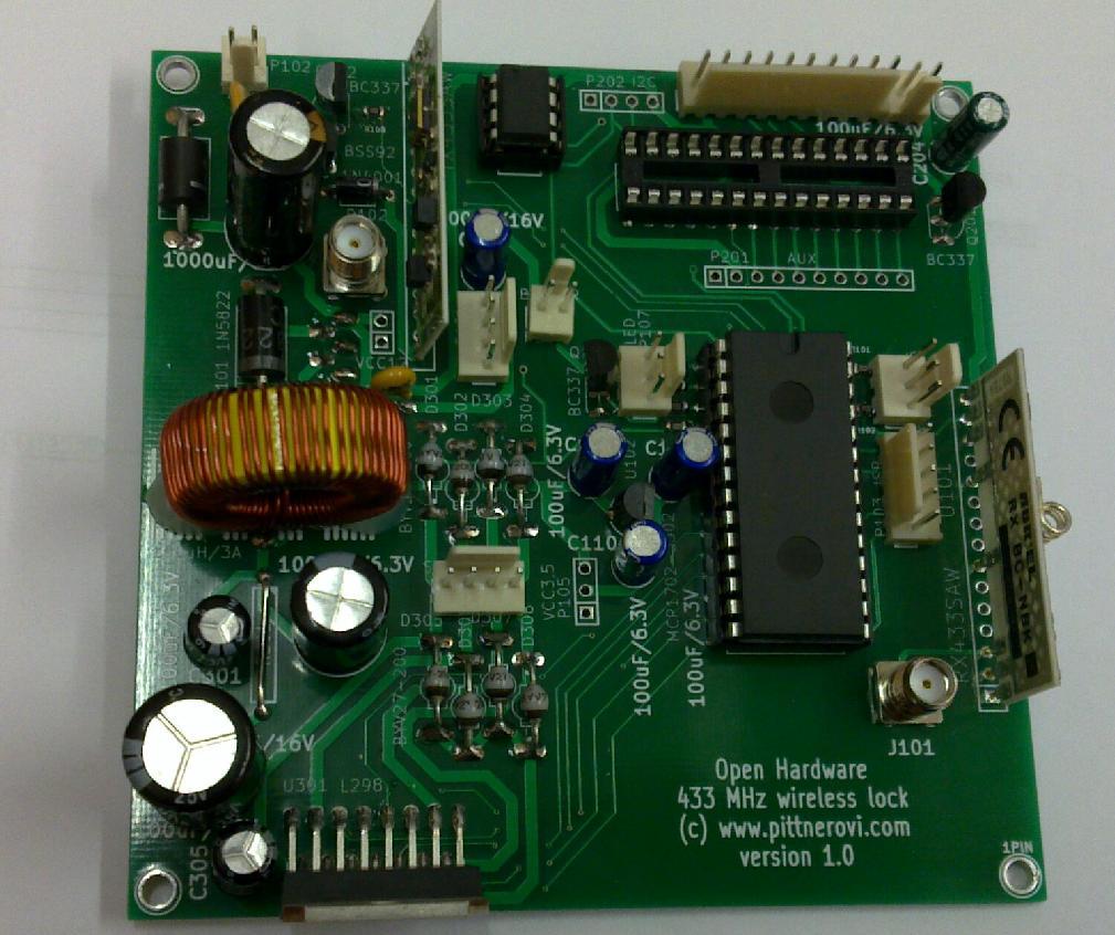
Note: LM298 should get a heatsink in the final installation
Note2: In the final setup, the wire jumper connecting 5V rail to step motor power rail was removed and the LM298/motor was powered from the 13.8V rail to get more torque.
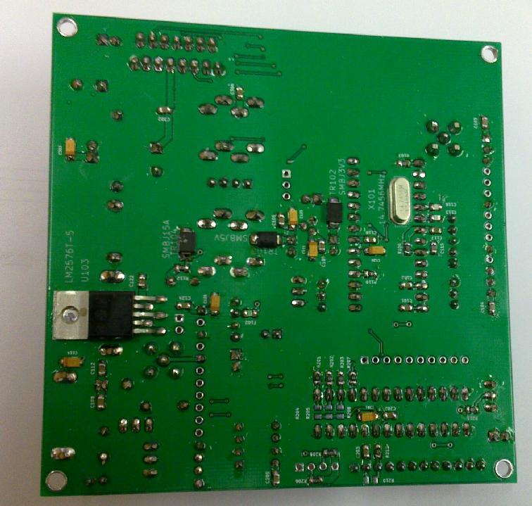
Lock PCB - back side
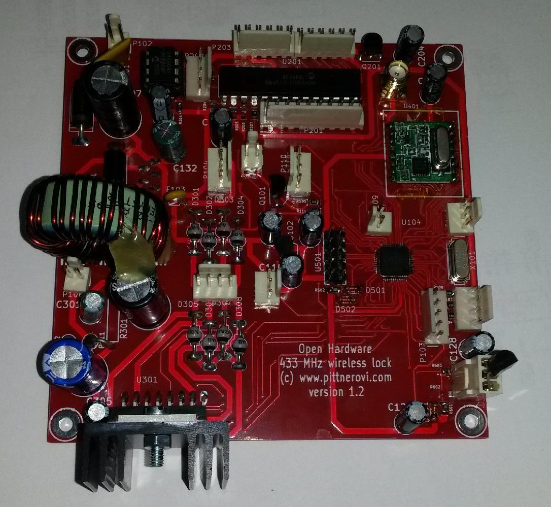
Lock respinned PCB - front side
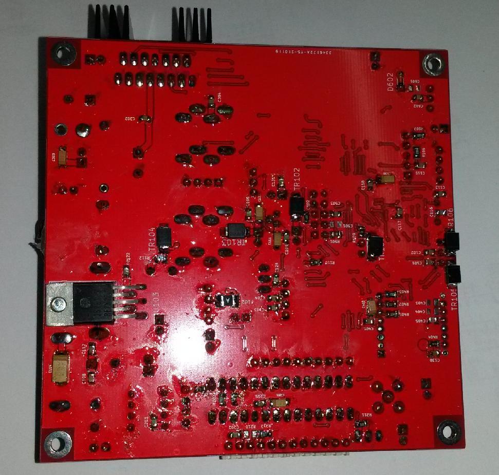
Lock respinned PCB - back side
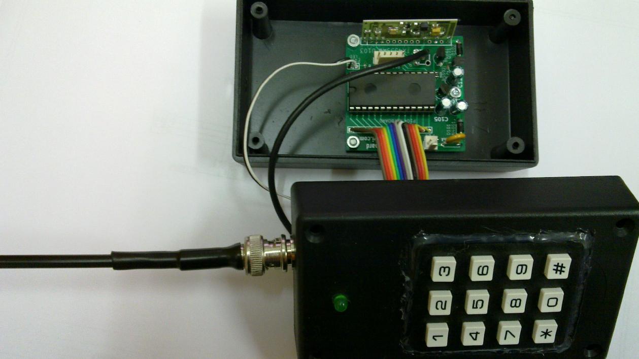
Keyboard
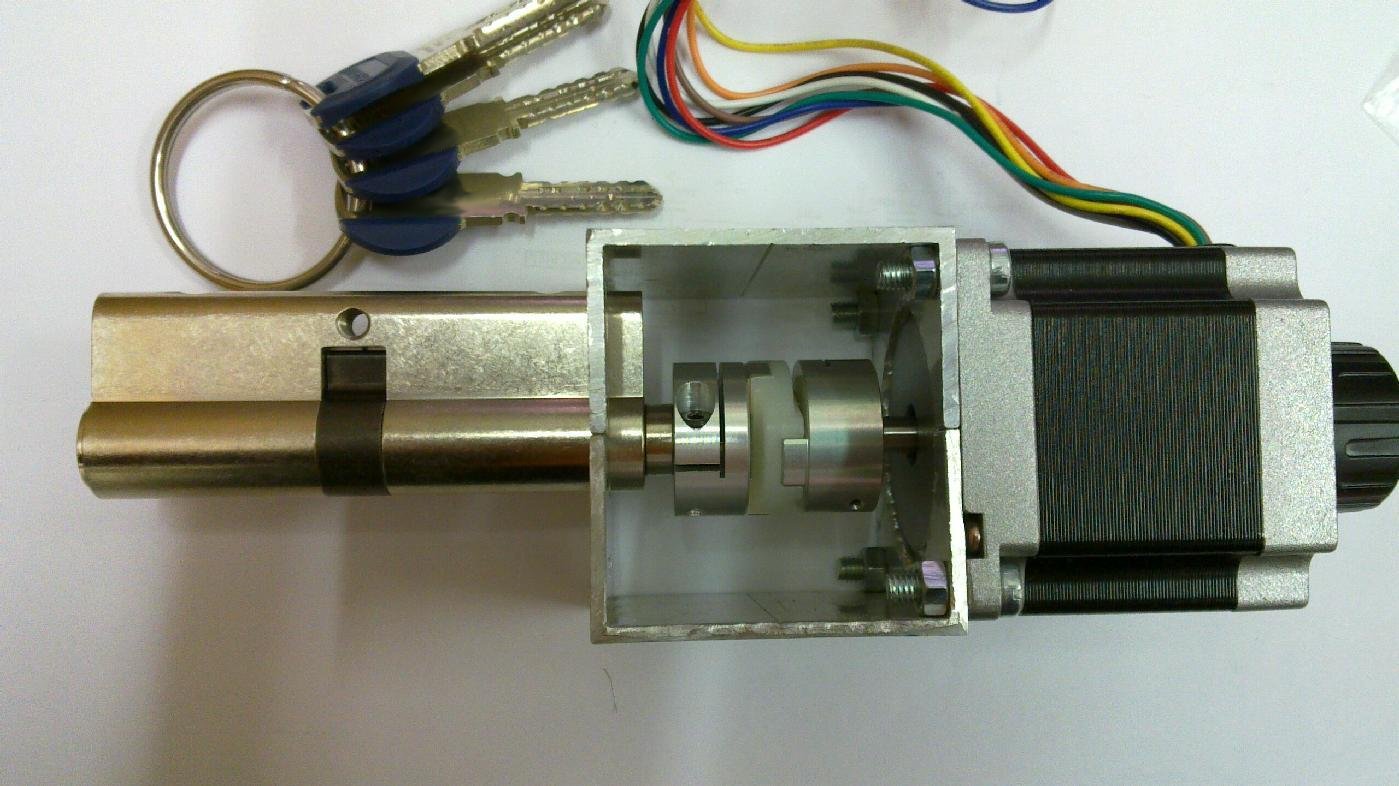
Step motor SX23-1012D (www.microcon.cz) connected via a coupling (www.huco.com) to a locking cylinder The step motor is now obsolete, SX23-1414D is a suitable replacement. I have seen a similar one also on Aliexpress, under the name ACT nema 23 stepper motor 23HS6620B, HUCO couplings are available there as well.
Final installation of the lock's mechanical part
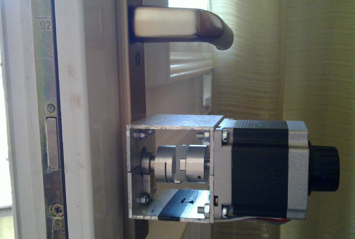
Notice the knob on the motor - for opening by hand from the inside in case of failure - special version of the motor with axis on both sides was needed. Opening from outside by a key in case of software/hardware failure is also possible.
Final installation of the lock's electronic part
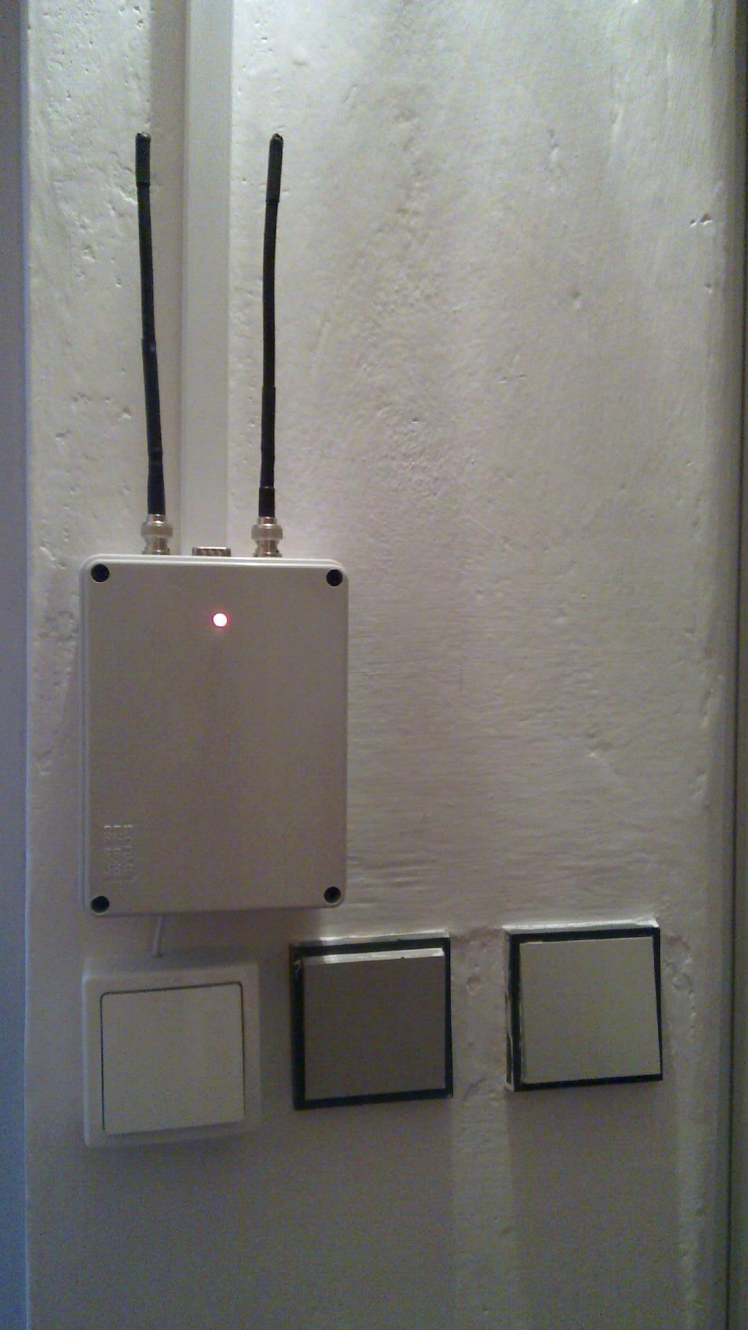
The box on the picture contains the control board of the lock, below is the open/close switch. Power supply and backup lead-acid battery is in a separate box located at a power outlet.
High security combined electronic and mechanical lock
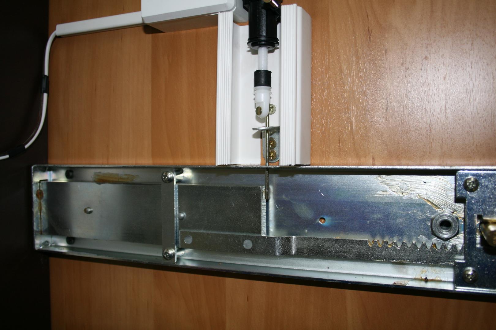
Obviously, the lock described above is only as secure as the mechanical locking cylinder, which represents a rather miserable security level - the electronic lock just provides flexibility, remote control etc. However, a different mechanical arrangement can be used to increase the security of the locking system. Instead of a step motor, it is possible to connect a linear motor from car's door opening system, and this can move a metal rod, which will in the locked state mechanically block a way of some locking bar of a heavy duty mechanical lock. Only a small modification of the code is necessary - the linear motor has a single winding (so even 2 such motors can be connected in place of the step motor to my board) and by sending about 0.5sec long pulse of varying polarity you lock/unlock it. You can get an idea from the picture below. The mechanical parts should be mounted under some cover, to prevent an attacker from an access via endoscope inserted after bending the door. Such an enhanced lock makes it almost impossible to break into the protected area without leaving traces.Mechanical setup increasing the security of the locking system
I was always puzzled how ignorant most people are concerning physical security of objects, not realizing how easy it is for a skilled expert with the rigth equipment (see e.g. here or here here ), be it a sophisticated thieve or a locksmith working for law enforcement, to open vast majority of mechanical locks without leaving any traces. During 2018-2019, lockpickers conquered even the sophisticated magnetic lock EVVA MCS, using either magnetic picks, or a decoder device and a 3D-printed plastic key with inserted miniature magnets oriented accoding to the decoded information. For more information see security.org by Marc Weber Tobias and his superb book Locks, safes, and security and the Schneier's blog. Another useful reference is the book by Graham PULFORD (2007) High Security Mechanical Locks: An Encyclopedic Reference. ISBN 0750684372. For an overview how locks of different manufacturers performed in bumping, lockpicking and other tests, see LOCKWIKI and also http://www.locks.su/test/test_full.asp (in russian) or english version.
Most electronic locks on the market are no better, using long-ago-cracked RFID technology, weak ciphers, or reasonable ciphers but with a poor key management scheme where a cryptanalysis of one device uncovers the manufactur's key and renders all its products unsecure - like commercial Keeloq based products. Fingerprint scanners can be fooled, too. The recently popular electro/mechanical locks like ASSA CLIQ have also been hacked by Marc Weber Tobias in a mechanical way, which circumvents the electronics completely (details of the procedure were not disclosed as of 2015). For example, in my country some people who commited multi-million level economic crimes and bribed polititians at the highest level were stupid enough to leave their officies so poorly protected that the police was able to enter them undetected and place bugs for eavesdroping. Of course, they possibly relied on a commercial security agency, which, predictably, will betray its client on a government agency request. So for real security, you have to rely only on yourself :-). I hope you are interested in the lock for lawful purposes ;-), but I think that (perhaps after updating the code to use AES and elliptic curves), and in connection with properly designed alarm system (not relying on a commercial product and security agency), this lock setup would prevent anybody from an undetected entry.
I have published a LPC1114-based thermostat as another software application for the same hardware board which uses the stepper motor to turn a valve open/close.
Introduction to LPC1114 programming and some related projects
My Electronics page
My hobby page
My main page with e-mail contact
TOP of my family pages