OBD2 CAN bus diagnostic device and datalogger (Open hardware and open source DIY hobby construction)
Obviously, there is a ton of OBD2 diagnostic tools and CAN bus convertors on the market, but I wanted to learn how this works in detail from the physical level up, so I constructed my own one from scratch, both hardware and software part. I present my design here under an open hardware/source license, since it might be useful or inspiring to others.Hardware of the CAN datalogger and OBD2 analyzer
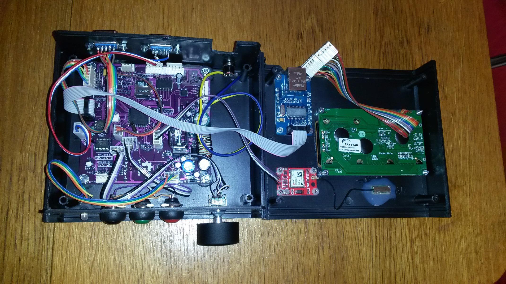
From the few microcontrollers I have a good experience with, the only one with CAN bus controller is STM32F37, so the choice was clear. The MCP2562 chip is used as a CAN transceiver on the physical layer. I already had a board design with this MCU for a simple avionics.Only a minor redesign of the board was necessary for this purpose. I decided the device should provice, besides the CAN bus interface, also 10baseT LAN, USB serial, USB mass storage, MicroSD card for data logging, real time clock, optional GPS, optional bluetooth, optional analog inputs, optional other I2C connected peripherals, alfanumeric display 4x20 with rotational encoder and buttons for user interaction. Power input from the car socket accepting anything in the range 5-30V DC.
The schematics in PDF is here, complete Kicad design files under the GPL license and production Gerbers are here.
Here is the resulting device
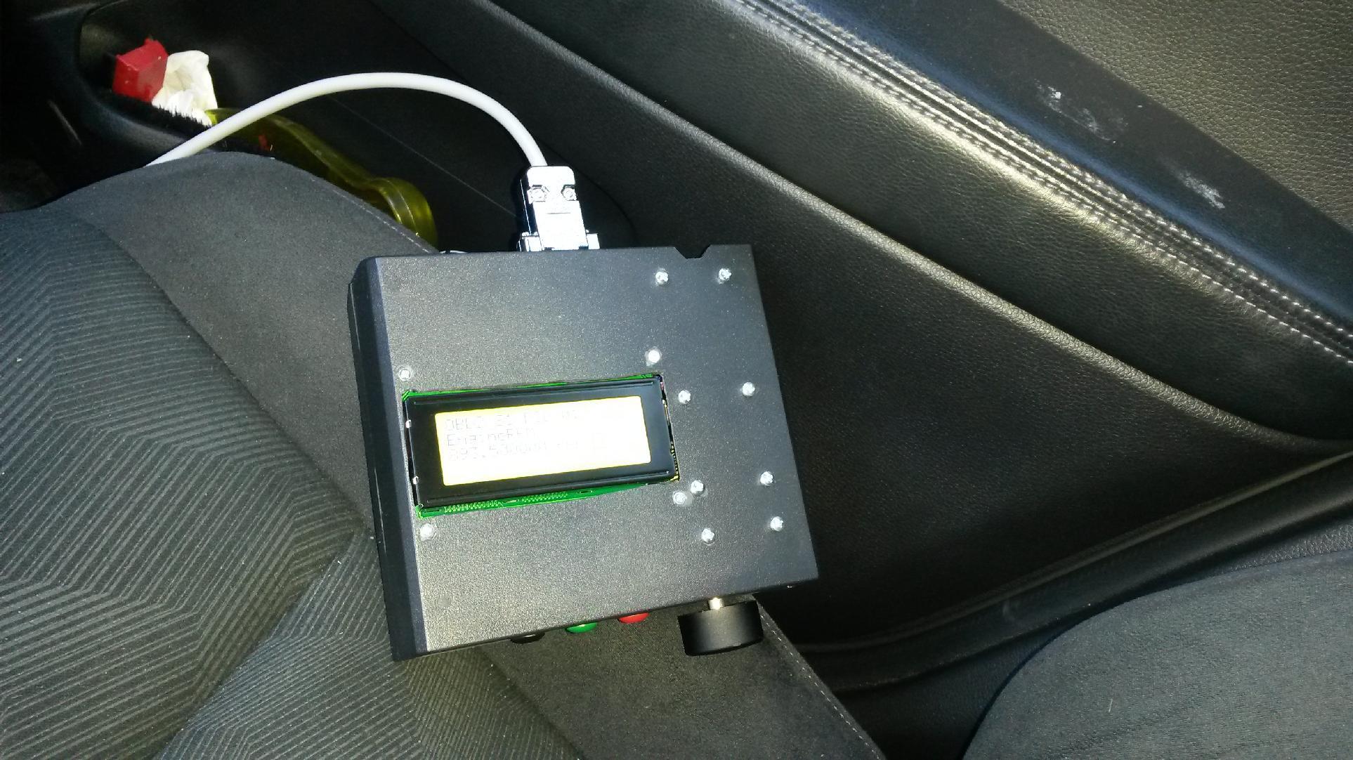
Here it is connected in the car and reading engine RPMs (sorry, the display was too bright for the camera)
Software for the CAN datalogger and OBD2 analyzer
I wanted to implement the following functionality: datalogging of all traffic on the CAN bus, or requested OBD2 traffic only, to the microSD card (FAT formatted) and standard output. The standard output being either USART1 (for debugging), USB serial (/dev/ttyACM0), or UDP "pseoudoshell" - two-way socket communication by UDP packets for remote operation. The device can work standalone, user selecting which OBD2 query to send, once, or repeatedly, displaying the results on the alfanumeric display and logging to the microSD, where it can be later accessed via USB when the device is switched to the mass storage mode. After each powerup, the device automatically opens a new logfile named by date and time of its opening. The real time clock is battery backed up and automatically adjusted when GPS signal is available. For the serial, USB, or UDP communication I use my program smsm2.c, but a generic serial terminal program and/or netcat can be used too.Concerning the setup of the CAN bus interface, I followed the standard STM32 library. I can achieve 500000baud, and lower /2 and /5 fractions with the MCU clocked by 12MHz crystal and PLL=6. It turned out that my car sends a lot of unsolicited messages and in order not to miss the OBD2 replies I had to employ the CAN hardware reception filtering provided by the MCU. Otherwise it was quite straightforward to implement the CAN OBD2 communication as described on the OBD2 wiki.
However, it would be too boring labor to program by hand the decoding of the OBD2 responses for all the PIDs, and I did not want to use C++ and existing Arduino libraries, but to stay with C and develop my own program. Fortunately, I have found the OBD2 decoding rules in the DBC format and decoding rules for some of the Nissan's unsolicited CAN messages. I also found that there exists a C code generator from the DBC format which makes a C code to decode these messages. However, for my taste the DBCC generated too large code and used unnecessarily large data structures, so I wrote my own DBC to C code generator DBC2C and can_devind.h, which I provide here under GPLv3. Using this code generator, I implemented support of the S1 and S2 OBD2 modes, as well as unsolicited CAN messages directly in the C code for the microcontroller. S3 and S4 modes are implementad by hand, as well as the reading of the VIN number. The build of the MCU executable, including the DBC to C translation, is completely automated using Makefile. The complete sources under GPLv3 are in stm32f37.tar.gz. Notice that the part of code which is not specific to the hardware is isolated in can_devind.* and together with the code generated from DBC can be used e.g. on a PC, with a simple USB-CAN adapter. The software support for other peripherals I have taken from previous projects, which are also contained in the tar file.
A sample log file, filtered for incoming OBD2 messages, is here.
My Electronics page
My hobby page
My main page with e-mail contact
TOP of my family pages