Starting with FPGA and CPLD hardware design in Verilog
Hardware description languages (HDL) have become indispensable for digital hardware design in the last decades; modern electronics would be really unthinkable without these powerful tools. Nowadays, this technology is quite accessible to hobbyists, since both Xilinx and Altera offer (the basic version of) their design tools free of cost, the price and availability of the chips in unit amounts is not prohibitive, and even the amateur soldering of QFN or BGA packages in not impossible, using e.g. adaptors from Schmartboard.com. For me personally an additional barrier was the restriction of the design tools for Windows only. However, Xilinx Webpack has become available in a Linux version some time ago.Since the installation of the complete Xilinx toolchain was not completely straightforward, nor finding out how to run it from a command line, which is my preferable way of work, I think that the following information might be useful for another novices in this field.
A very useful document about developing code for FPGA using command line tools, which I recommend you to read, is FPGAs at the Command Line by Bob Smith. Below I give some instructions based on this article, however, for a DIGILENT Spartan-3E XC3S1600E board and I am including also the command lines to upload the code to FPGA or to EEPROM memories on the board and to perform simulations, which were not described in this article. Moreover, I present an analogous command sequence for CPLD design, in particular XC9572 in PLCC44 package, which I soldered on an experimental board myself.
HOWTO install the Xilinx Webpack and JTAG drivers on Linux
I installed version 12.4 some time ago; for more recent ones it should be analogous. I did the installation on an old laptop with 32-bit system, some time later I just transferred everything to a new one running 64-bit Gentoo with multilib and everything worked smoothly, so do not be afraid of running it on a 64-bit Linux.
1. Download the Webpack from Xilinx and install it using the provided instructions
2. Do NOT install kernel drivers for JTAG cables from Xilinx.com;
instead install the userspace USB driver written by Michael Gernoth
Follow the steps from the README file there, in particular you will need to install the 'fxload' package in your distro, copy files from path/to/ISE/bin/lin/xusb*.hex to /usr/share/; install xusbdfwu.rules to /etc/udev/rules.d (and possibly to modify it as described in the README); and in /path/to/ISE/bin/lin/ mv _impact _impact.bin and create a script _impact containing the command "LD_PRELOAD=/opt/Xilinx/usb-driver/libusb-driver.so $0.bin $*"
3. Add the following to your .profile/.cshrc: (use settings32.sh for bash of course and change the version number if needed)
source /opt/Xilinx/12.4/ISE_DS/settings32.csh; setenv PATH /opt/Xilinx/12.4/ISE_DS/ISE/bin/lin:$PATH; source /opt/Xilinx/12.4/ISE_DS/EDK/settings32.csh; setenv PATH /opt/Xilinx/12.4/ISE_DS/EDK/bin/lin:$PATH; setenv PATH /opt/Xilinx/12.4/ISE_DS/EDK/gnu/microblaze/lin/bin:$PATH
All the following scripts assume that the Xilings settings file has been sourced and the path has been extended appropriately!!!
NEW: It should be possible to avoid the proprietary "Impact" and program the Xilinx chips using the open source programs xc3sprog. Once I have time to try it, I will write about it here :-).
HOWTO Compile a Verilog code for Xilinx FPGA using Linux command line
rm -rf xst/work #cleans old generated filesecho "run -ifn $1.v -ifmt Verilog -ofn $1.ngc -p xc3s1600e-fg320-4 -opt_mode Speed -opt_level 1" | xst #translates Verilog to generic netlist .ngc file
ngdbuild -p xc3s1600e-fg320-4 -uc $1.ucf $1.ngc #translates the netlist to native FPGA elements and takes into account pin assignment from the ucf file
map -detail -pr b $1.ngd #translates it to elements of the specified target
par -ol high -w $1.ncd $1.par.ncd #place and route step
bitgen -w -g StartupClk:Cclk $1.par.ncd $1.bit #generates the .bit file to configure the FPGA
promgen -w -x xcf04s xcf04s -p mcs -o $1.mcs -u 0 $1.bit #translates the bit file to a form suitable for the eeproms (split in two pieces for two EEPROM chips of smaller size on this board)
The compilation script is here (compileme) ; a ``hello world'' type Verilog example is here (muj5.v) and a suitable ucf file for the Spartan-3e Digilent board is here (muj5.ufc) .
Just run 'compileme muj5'.
To upload the resulting .bit file to the board, use the script upload: 'upload muj5'. This (and the UCF file) has to be modified for other boards, of course. Notice that you have to declare in the script all devices in the JTAG daisy chain, otherwise impact will report mismatch between part identifiers and their bit patterns will be obviously shifted.
To upload the MCS files to the eeproms, use this script eeupload: 'eeupload muj5'.
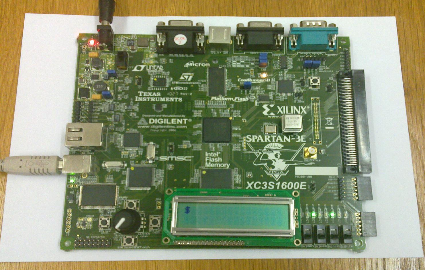
I am using this Spartan3 development board from Digilent for experiments with FPGA.
HOWTO Compile a Verilog code for Xilinx CPLD using Linux command line
For CPLDs, the procedure is similar, but steps after ngdbuild are different. The compilation script is given here (compileme_cpld) and a sample UCF file is here (muj5_cpld.ucf). The Verilog source is identical to the previous example. Notice that I am programming the CPLD using a JTAG programmer ASIX Presto, so I use Impact to dry-run the programming, which generates a .xsvf file (or .svf file for other targets), which is then "replayed" by the actual programmer (in my case running the proprietary jtagplay.exe under wine). This step you have to change depending on your JTAG adaptor.
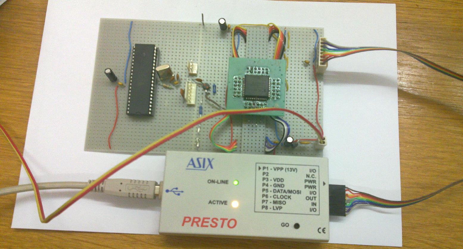
Here is my quick and dirty CPLD testing board with XC9572 and ATmega16, which serves as clock source and testbench for the CPLD.
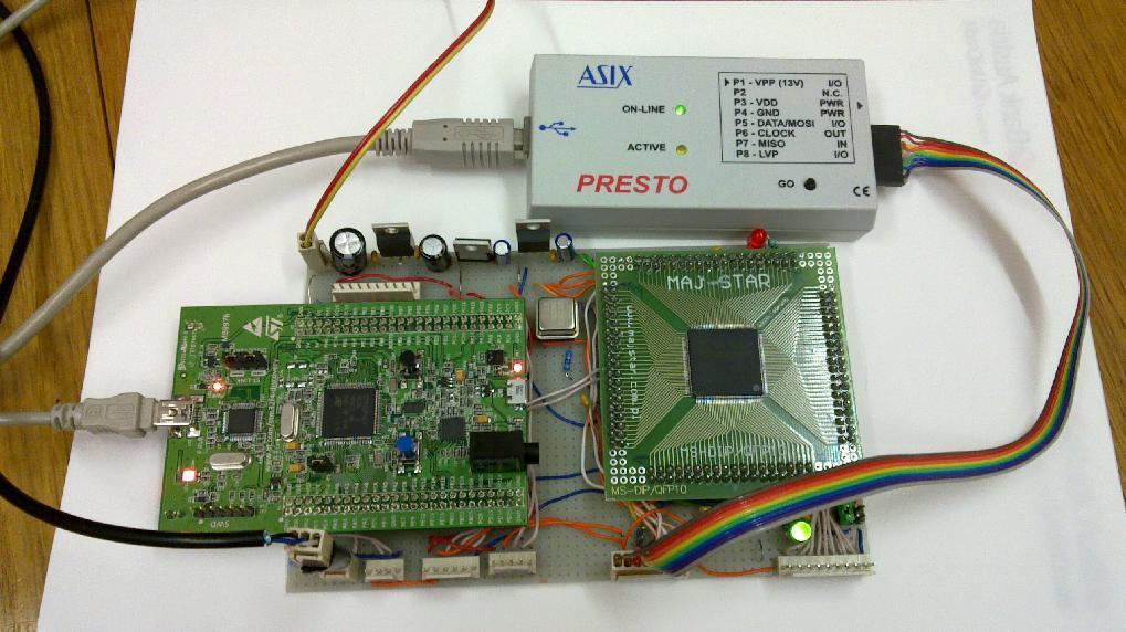
Since XC9572 is not big enough to fit anything remotely complex, I have also made a similar board with the Spartan 3 XC3S50AN, which can be easily hand-soldered and has a non-volatile configuration flash on chip, so the only thing you have to provide is 3V3 and 1V2 power and bypass capacitors. Jumpers on the M0-2 pins are used to select configuration from internal flash, suspend is pulled down, DONE goes to the red LED via 470R. On the board it is combined with the inexpensive STM32F4 discovery kit, to test e.g. I2C or SPI slave cores in the FPGA.
To compile verilog for this FPGA I use this script and to flash the configuration via JTAG this script .
HOWTO simulate a Verilog design with Xilinx iSIM using Linux command line
Of course, for non-trivial designs one does first simulate the design, before pushing it all the way to hardware. This can be conveniently done partly by command line, partly in a GUI (waveform inspection). A script which creates an executable file, which in turn runs the simulation is here (simulateme) and a testbench suitable to the previous example is here (muj5test.v). Just run "./simulateme muj5test muj5" and then start ./muj5.exe -gui, start the simulation and inspect waveforms in the GUI.
I did not advance enough to perform timing simulations yet, maybe a little script for that will appear here in the future...
HOWTO simulate a Verilog design employing free software (open source)
If you want just to play with Verilog without really going to the hardware, you can stay in the realm of free software, no proprietary tools from hardware vendors are needed. (Well, you can learn Verilog without touching any piece of hardware except your keyboard and mouse, but it is like riding on a stationary bicycle, just exercise, no fun:-)). Here is another "hello world" Verilog example together with its testbench (simul1.v).
To run the simulation, you do not need to install anything from Xilinx. Instead, install the packages "iverilog" and "gtkwave", which are probably part of your Linux distribution (they are available e.g. in Gentoo).
Then run the following commands:
iverilog -o simul1.vvp simul1.v
vvp simul1.vvp -vcd
gtkwave dump.vcd
and inspect the waveforms in the GUI.
Notice also that iverilog can be used instead of xst to compile the Verilog code, replacing the Xilinx xst (I did not test this yet):
iverilog -parch=spartan3 -o foo.edf foo.v
edif2ngd foo.edf foo.ngo
ngdbuild -p xc3s1600e-fg320 foo.ngo foo.ngd
Further steps are the same as before.
For a newcomer to Verilog coding I would recommend the book "FPGA prototyping by Verilog examples" by Pong P. Chu (Wiley 2008, ISBN 978-0-470-18532-2), which is very practically oriented and well understandable, really excellent for a self-study. Very useful is also the library of open source Verilog (and VHDL) "IP cores" at opencores.org. Obviously, becoming really good in Verilog coding requires much practice. I must say that I did not have enough time (and real motivation) to become expert on this field (and probably I will never have), but I definitely wanted to learn a bit about Verilog to at least roughly understand how a simple processor can be implemented, or how FPGAs are used in devices like USRP or Proxmark. (The latter was also the main reason for my preference of learning Verilog rather than VHDL.)
My Electronics page
My hobby page
My main page with e-mail contact
TOP of my family pages