Measuring inductor saturation by a time domain method
In power electronics, it is essential to make sure that the inductance of a choke will not decrease too much due to core saturation at the working current. There are basically two possibilities how to measure it - "statically" by using a usual LCR meter but providing DC current bias to the inductor, or "dynamically" by measuring the dI(t)/dt curve after connecting the inductor to a hard voltage source and checking its (non)linearity.The former method is simpler so I choose it first, see here.
Open hardware inductor core saturation tester schematics and Kicad design
The remainder of this page is concerned with the dynamical approach. The quick way is of course just to use an oscilloscope, but I liked to design a device which would be more comfortable to use, displaying directly the values like current for which inductance halves directly on display, and possibly uploading the measured data to PC for graphical display and further analysis. Also the dynamical method is more practical for high test currents than using high DC current bias.
I was considering whether it is necessary to employ fast ADCs and FPGA and SRAM in a way an oscilloscope works, but came to the conclusion that for typical inductance values employed in power electronics it would be an overkill and that about 500ks/sec should be sufficient, if relatively low test voltage is used. For example, connecting 100uH inductor to 2V source yields 20mA/us slope, so should the inductor be rated to 1A, at 0.5Ms/s we get 25 samples before saturation which should be enough. The peak ADC sampling rate available in , my favorite STM32F37 microcontroller series, is 1Ms/s, so it should be sufficient.
I have thus designed open hardware Kicad schematics and PCB of such an inductor saturation tester. For convenience you can view the schematics also in PDF format. The operating principle is as follows: one DAC controls a DC/DC step down power supply for the testing voltage ( details here). A P-channel power MOSFET switches this voltage on the DUT inductor. The current then goes through a 0.1R or 0.01R shunt and the voltage is optionally amplified by an op-amp and measured by a fast ADC. Second DAC prepares a threshold voltage for a comparator, which implements current limiting via discrete hardware logic, to be fast, which is placed between GPIO control pin and the P-mosfet.
I considered also using op-amps to compute the current derivative in analog, but finally dropped the idea to keep the circuit simple (it would have to be done for each channel, and probably would require also a dual power suplly for the op-amps). With a 12-bit ADC I hope one can get sufficient accuracy in the numerical derivative.
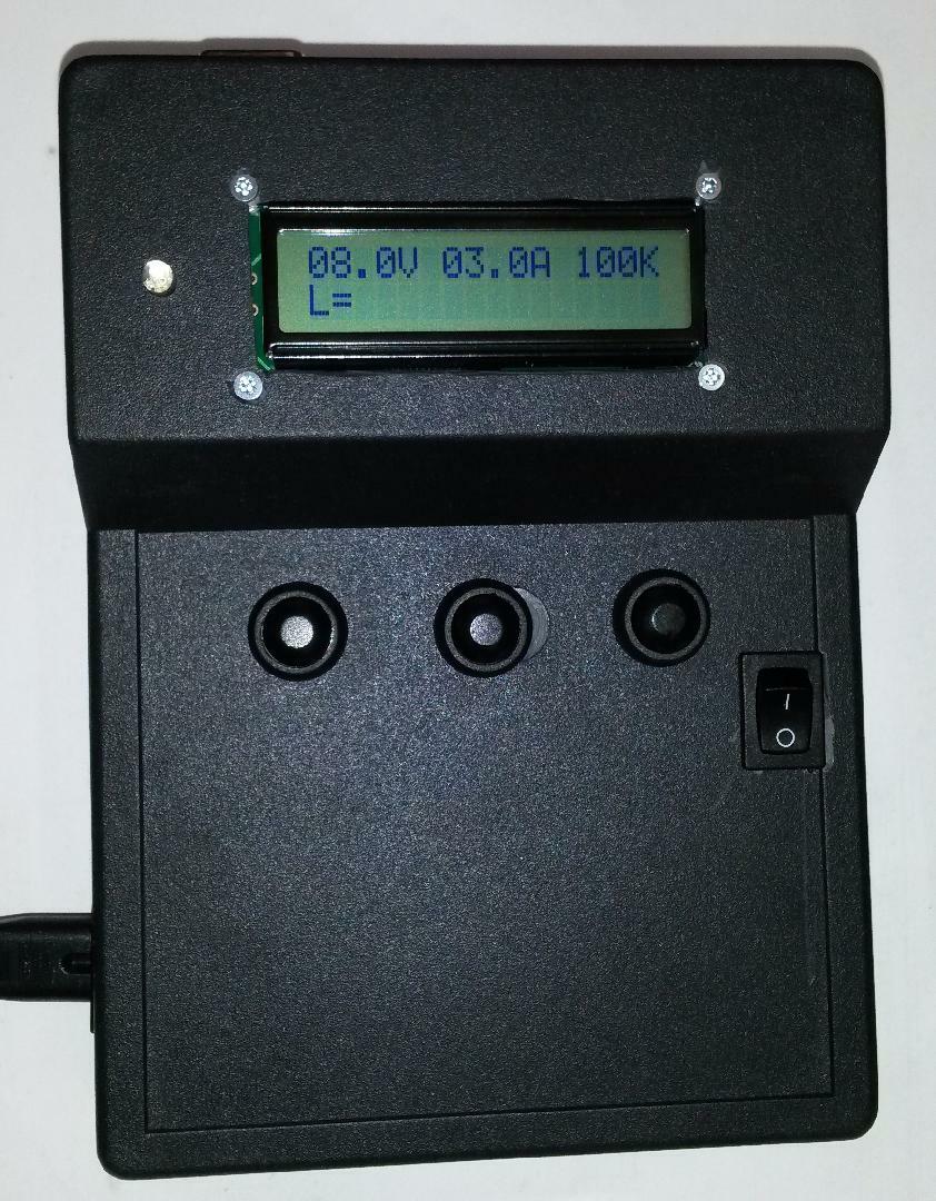
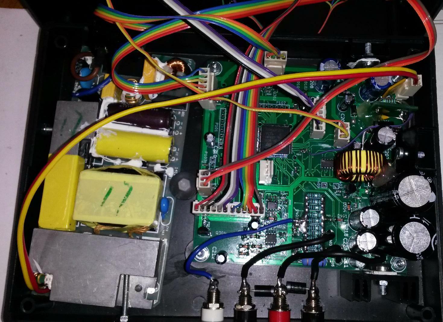
On the photos below you can see the complete device and inside. You can notice patches on the board, I did not get it all right the first time (should have been reading datasheets in more detail ;-)), but the Kicad design on this page contains all the corrections to hardware already. On the left you can see the mains power supply, which was taken from a 3A rated laptop DC adapter and its voltage was lowered to about 15V by a change of one resistor.
GPL open source firmware for the inductor core saturation tester
The principle of operation is as follows:Inductor with internal resistance R and inductance L connected to voltage source U:
U = RI + L dI/dt
Indicating explicitly functional dependences:
U(t) = RI(t) + L(I) dI(t)/dt
for analytic solution assume U(t)=const, L(I)=const, then
I = U/R * (1-exp(-Rt/L))
In limit L=0 : I = U/R
In limit R=0 : I=U/L*t
However, as core saturates, L(I) is a general nonlinear function. Moreover, U(t) is not constant since our capacitor bank is not infinite We could measure U(t) along I(t), at the expense of halving the effective sample rate (presently not implemented). Note that R = Rsense + R_L if we take Vup as U. Since R_L should be small and can be measured by DC milliohmmeter, we take it as an optional external correction (its determination from measurements by this device is difficult, since we do not have a constant current source), with default 0. Then we get for the inductance
L = (U-RI)/I' where I' is dI/dt
We sample I(t) at a equally spaced time grid with finite "dt" and approximate the derivative by finite difference.
The main firmware program 'saturation.c' with all other files needed is in stm32f37.tar.gz archive. Parts written by myself are under the GNU GPLv3 license, STM hardware libraries are under their license.
The use of the device is very simple - by a switch toggle between the high/low current measurements and connect the inductor to appropriate sockets. Then press middle button to start, and the to erase displayed data and start again. Left and right button can be used to change measurement parameters like voltage, max current, sampling frequency etc. There is a GND socket to connect a scope probe if you want to see the voltage/current on the inductor graphically. The device shows on the display min and max inductance in the current interval measured, inductance at half of the max current and average of inductances in the smaller-I half of the measured interval. More data is printed at the serial USART port. If 'nan' is shown instead of numerical values, or the max inductance value differs much from a measurement by a LCR meter with a small amplitude AC, the measurement parametes are not appropriate for the given inductor and have to be changed accordingly. There is no autoranging feature. The device supports also USB communication with a PC - just connect USB, power the device, then start a terminal program on /dev/ttyACM0 or a windows-equivalent and send 'enter' into the terminal, to switch from USART to USB output.
My Electronics page
My hobby page
My main page with e-mail contact
TOP of my family pages