RF electronics - a GPL-licensed open source C++ program for calculation of impedance matching networks and other RF amplifier design parameters from s-parameters
Since the calculation of impedance matching networks is necessary even for the simplest RF hobby work, and I did not want to rely on online calculators, which might disappear after a while, I wrote a simple program myself, based on Chapters 4-6 of the Bowick's book "RF circuit design". At the command line, matching network topology can be chosen: default is L-shape, -L chooses double-L; -T Q and -P Q select T- and Pi-shape with a specified Q value, respectively.Note that when absorbing the reactance into a LC network matching the real components, the sign of the network's reactances can flip; such cases are not discarded but printed as well.
Other quantities relevant for the RF design are computed as well - stability circles, available gain, constant gain circle for requested gain, etc.
The matching networks are desiged for conjugate input/output matching (nonzero S12), or unilaterally under unstable conditions or when requested by command line option.
I also wanted to properly learn the topic, and writing my own code to do it is always my preferable way of learning such a topic in detail :-). The code reads input consisting of lines giving frequency a s-parameters each, and computes all possible versions of matching networks for input and output to 50 ohms and the other data. The source code sparameters.cc is GPL-licensed.
A sample input file RF2126.s2p contains S-parameters for the (now obsoleted) amplifier RF2126, courtesy of Qorvo (former RFMD).
Sample of the output:
f = 2.54078GHz:
Unilateral impedances Zs = (7.71272,23.05719); Zl = (8.55952,11.93083)
Conjugate match impedances Zsm* = (10.54878,21.41002); Zlm* = (12.36056,10.00967)
Stability=1111
Max av. gain = 10.4 dB; power gain = 10.4 dB; available power gain = 10.4 dB; transducer power gain = 10.4 dB
L-Matching input to Z0:
serial C=62.02pF parallel C=2.42pF Q=1.93;
serial C=1.50pF parallel L=1.62nH Q=1.93;
parallel C=2.68pF serial L=0.89nH Q=0.28;
parallel C=2.03pF serial C=4.43pF Q=0.28;
L-Matching output to Z0:
serial L=0.72nH parallel C=2.19pF Q=1.75;
serial C=1.98pF parallel L=1.79nH Q=1.75;
Using this program, I have designed a RF amplifier with RF2126.
NOTE: Useful open source programs and online calculators for RF design (antennas, filters, matching) can be found at WA4DSY.net.
RF electronics - using USRP as a simple antenna analyzer
The RF electronics is a particularly challenging and interesting, since it is more difficult than DC or low frequency circuits. Today's technology of cell phones, digital TV broadcast, wideband wireless internet etc. would not be possible without great advances of the RF technology.
As a useful source of information on this topic I can recommend the following books:
Joseph F. White: High frequency techniques: an introduction to RF and microwave engineering, Wiley 2004, ISBN 0-471-45591-1
David M. Pozar: Microwave engineering, Wiley, 2012, ISBN 978-0-470-63155-3
Chris Bowick: RF circuit design, Elsevier, Amsterdam, 2008, ISBN-13: 978-0-7506-8518-4
Arthur B. Williams, Fred J. Taylor: Electronic filter design handbook, McGRAW-HILL, New York 2006, ISBN 0-07-147171-5
Fuqin Xiong: Digital Modulation Techniques, Artech House, 2000
Jon B. Hagen: Radio-Frequency Electronics, Cambridge University Press, 2009
Ian Hickman: Practical Radio-Frequency Handbook, Newnes 2002, ISBN 0-7506-5369-8
Joseph J. Carr: Secrets of RF Circuit Design, McGraw-Hill 2000, ISBN 0-07-137067-6
The books are roughly ordered from the most theoretical one to the most practically oriented one. The first two books bridge the gap between abstract classical electrodynamics classes as usually taught at non-technical universities and the ``practical engineering'' approach based on lumped element circuits, network analysis, impedance matching, etc. The last one on the other hand gives particular advice towards practical RF construction (starting from the really elementary matter, like soldering of coaxial connectors), while the approach of the second one lies somewhere in the middle. So they are to a large extent complementary and all three are worth reading. Later I found another excellent book on high frequency electronics - David M. Pozar: Microwave engineering, Wiley, 2012, ISBN 978-0-470-63155-3, which discusses almost all topics ranging from Maxwell equations to microwave ovens.
An excellent text are also the PDFs from a course at Berkeley.
For a hobbyist there is another hurdle, the availability of test equipment - professional equipment for RF measurements is excessively expensive. However, a low cost vector network analyzer suitable for hobbyists is now available: MiniVNA Pro. It works up to 200MHz and with the recently available frequency extender up to 1.5GHz. I have recently acquired the device and I am very satisfied with it, definitely I can recommend it to hams or other hobbyists interested in RF. In particular, it works flawlessly under Linux (as expected from a java program).
While I definitely cannot claim to be a RF expert, I did some hands-on hobby experimenting, from which the following topic might be of some interest, so I posted it here.
How to make a simple antenna for GSM, using USRP as antenna analyzer
When doing some experiments with GSM using the USRP, GnuRadio, and OpenBTS, I needed some omni-directional antennas suitable for the GSM 900 and 1800 bands. I decided to construct them myself, using USRP and a directional coupler as a simple replacement of an antenna analyzer. I have used a directional coupler for UHF-SHF frequencies from EME Precisions, model no. 2320/30 (which works with higher attenuation even at about 100MHz), two 30dB attenuators for DC-2GHz from Minicircuits, and RGC54 coaxial cable to which I soldered SMA, BNC, and N connectors myself.
The experimental setup looks like this:
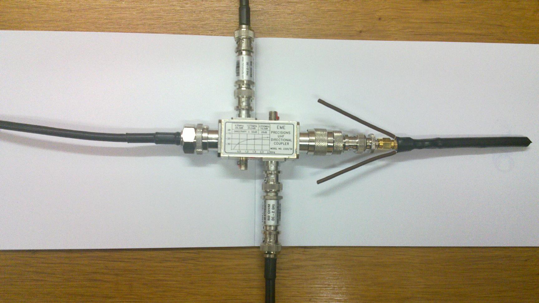
The input to the directional coupler is connected to the TX output of the WBX daughter-board of the USRP, the attenuated output of the direct wave from the coupler goes to the RX input of the WBX daughter-board, while the attenuated output of the reflected wave from the coupler goes to the RX input of another receiver daughter-board, in my case TVRX or DBSRX, depending on the frequency.
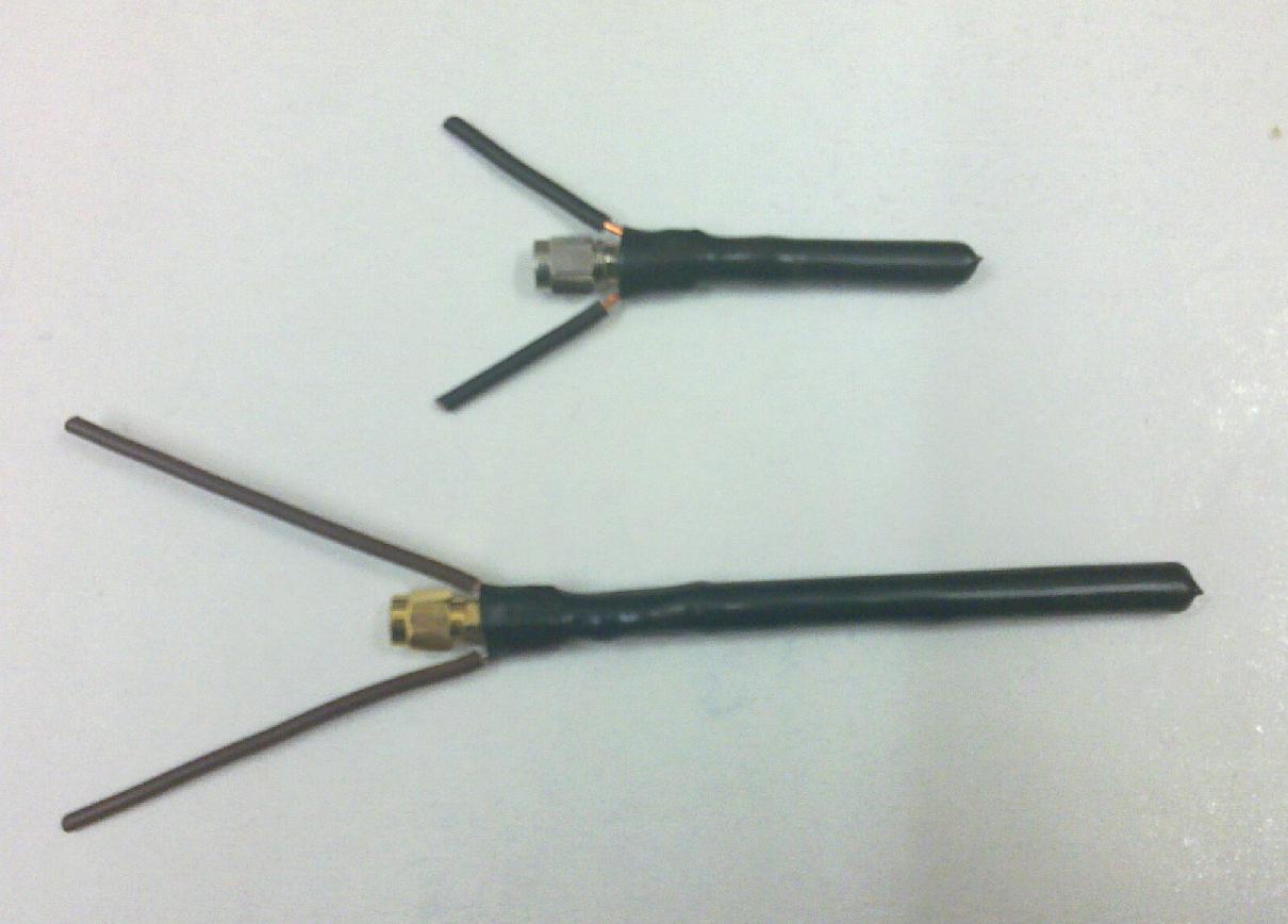
The antennas are constructed from a piece of RGC54 (H155) coaxial cable, crimped into a SMA connector. I have cut the shielding of the coaxial cable next to the crimped SMA, and connected the outgoing part of the shielding to the central wire and enclosed the antenna element in a heatshrink tubing. To the crimped part of the SMA connector two wires are soldered to form the counterpoise of a GP antenna. The length of all three antenna elements should be made longer than 1/4 lambda and the antenna is then tuned to yield minimum signal of the reflected wave at desired frequency by cutting it millimeter by millimeter.
When having everything assembled, I did run the following simple code in GnuRadio (GRC) analyzer.grc. It is really bare minimum, quick and dirty - I have fixed one frequency, unmounted the antenna, tuned the TX power and RX gain to get strong enough signal on the FFT display, then connected the antenna and cutted it to minimize the reflected signal strength. In this setup the direct wave from the coupler is actually not used. The code could be generalized to sweep over a frequency interval of interest, calibrate on the strength of the direct wave (since both TX power and RX gain of the USRP daughter-boards are frequency-dependent), then measure the signal strength of the reflected wave. But I did not have enough time and motivation to develop it so far, so I did just the single frequency measurements and antenna "tuning".
The resulting antennas look like this:
After I had the MiniVNA with extender available, I have checked the 900MHZ antenna using it and confirmed that the aforementioned procedure really did yield minimum of SWR at the correct frequency. Nevertheless, the USRP-based procedure is not obsoleted by MiniVNA, since with WBX and SBX daughterboards it is possible to go to much higher frequencies than available even with extender for MiniVNA.
Later I have found another web page on the topic of using USRP as a scalar or vector network analyzer.
Another interesing link on related topic: Software Defined Radio with HackRF .
Recently, I have obtained LIMESDR (supporting it by Crowdsupply) and did some experiments with it.
My Electronics page
My hobby page
My main page with e-mail contact
TOP of my family pages