Power regulator for a 1W Blue LED laser (a DIY hobby construction)
The laser LED technology incredibly advanced in the last years and powerful laser LEDs are now available on e-bay in the price range below USD100 including simple optics. Many photos and videos of toy experiments with such laser are on the internet, for example on Danyk's page. I have thus decided to make such a toy for my children myself (of course to be used by the kids only under supervision :-)). I have purchased a blue laser LED which should yield about 1.5W at 1.8A max allowed current, with a copper housing and optics. Update: As of 2016, 3.5W blue laser diodes are available on eBay for an affordable price. The Moore's law seems to be valid also for the power of solid state lasers, let's see where we will be in 10 years :-).The laser LED needs a constant current power supply to operate properly and prevent its damage. Suitable modules can be found on e-bay, but I wanted to make a regulated current supply to change the laser power from tens of milliwatts up to the full power by a potentiometer, to power it from batteries, and to use a switched mode power supply rather than a linear one for efficiency. I have thus designed my own schematics around the NCP3065 chip, which is a constant current switched mode controller. I have used an external P-MOSFET IRF4905 as a switching transistor to allow higher current and avoid overstressing the internal FET in the chip. Current sensing resistor 0R15 is used to allow max current about 1.6A, somewhat under the maximum allowed for the diode. Operating on 4xAA cells, only something over 1A was achieved, probably due to losses in the switching circuit, however, with external power supply of about 7V and higher the full current was achievable. Unfortunately, more batteries did not fit into the a priori chosen box. To get lower currents, a non-inverting amplifier with 1-11x gain based on LM258 is employed, which amplifies the voltage on the 0R15 resistor and feeds the result into the comparator input of NCP3065.
I did not design a PCB for this project, which was very simple to build on a piece of universal prototyping board. However, I have captured the schematics a posteriori in KiCad and I am providing it here under the GNU GPLv3 license, so it can be considered "open hardware". The schematics can also be view in a PDF file.
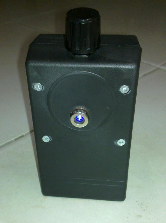
The mechanical design was simple - I have glued the LED module using a heat-conductive epoxide glue into a hole drilled in an aluminum heat sink. This unit was then mounted inside a small plastic box, together with batteries and PCB.
The finished "laser-pointer", with the power regulator on the top
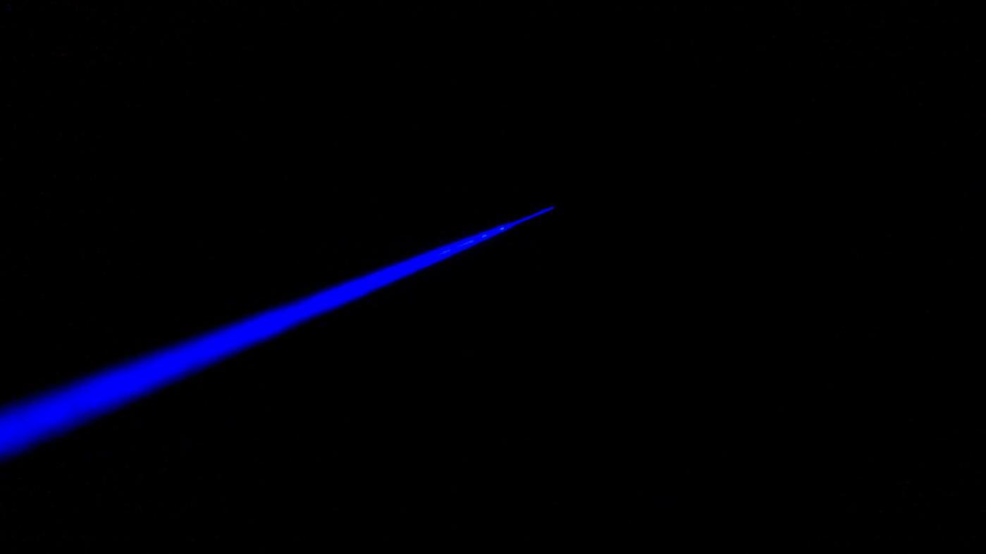
Laser beam in the night
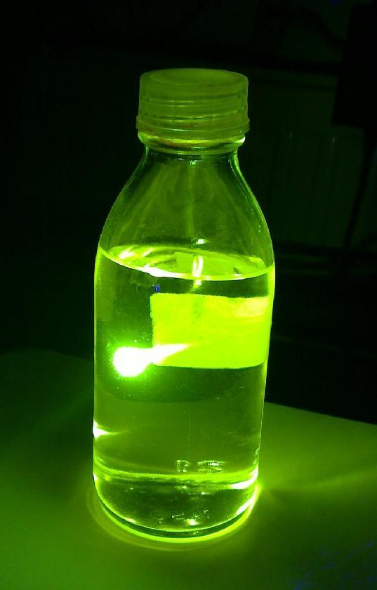
Fluorescence of a fluoresceine solution excited by the laser beam
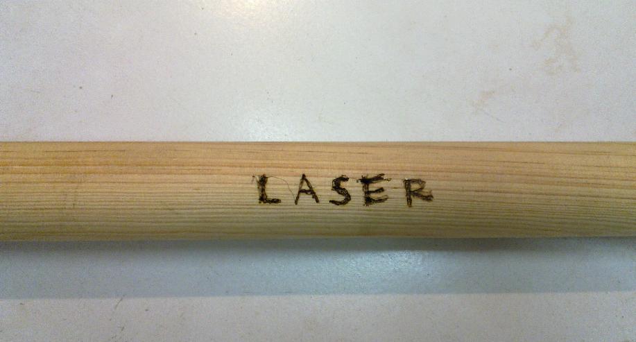
Writing on a surface of wood
Disclaimer: the author of this page is not responsible for any harm you can do yourself and others following the instructions here. Lasers of this power class are extremely dangerous to the eye, harmful to the skin and can ignite combustible materials: be careful, wear protective goggles, and don't do stupid and/or illegal things.
Back to my electronics page
Back to my hobby page
Back to my main page
TOP